192-011006N8 PSD1 Installation Guide
192-011006N8 2019-07
09.10.19 09:27
27 (109)
In this chapter you can read about:
•
Before commissioning the drive, please observe the following: ................................................. 27
•
Mounting and dimensions ......................................................................................................... 27
•
Connector overview PSD1-S .................................................................................................... 28
•
P14: Status LED (PSD1-S) ....................................................................................................... 31
•
X17: Digital Inputs / outputs (PSD1-S) ...................................................................................... 32
•
Wiring of the digital inputs and outputs ..................................................................................... 33
•
X63: AC Mains Supply, DC voltage supply & Connection of braking resistor (PSD1-S) ............ 33
•
X52: Motor connection (PSD1-S) .............................................................................................. 35
•
Motor feedback ......................................................................................................................... 36
•
X60: PC-/Diagnostic interface ................................................................................................... 38
•
Communication interfaces ........................................................................................................ 39
4.1
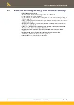
Before commissioning the drive, please observe the following:
CAUTION: Risk of electric shock
Caution - Risk of electric shock!
Before wiring or loosening electrical connections please observe the
following:
•
Risk of electric shock, disconnect power before removing cover resp.
disconnect the devices from the mains supply.
•
Caution!
Dangerous electrical voltage even after turning off the intermediate
capacitors:
Up to
3 minutes with PSD1-S and 10 minutes with PSD1-M
after switching off
mains supply, dangerous voltages may still be present.
Please check that no voltages are present (<50 V) at the output terminals DC+
and DC- of PSD1-S: X63/3 & X63/5 and with PSD1-M: Bus HV DC - 3 & 5. rail.
Only qualified electrician may commission the drive.
Accident prevention measures must be observed.
Please make sure that no small parts (screws, cable remnants, ..) enter the
devices.
Feedback system can be destroyed if configured incorrectly!
If you connect a PSD that has already been configured for a specific feedback
system to another feedback system, it can be destroyed by too high a voltage.
Procedure when changing the feedback system.
4. Installation of the individual drive
PSD1-S


