English
4/20
PSE 325-1000 60Hz
Y
Make the connection to the draining system, avoiding connection in a closed circuit shared by
other pressurized discharge lines. Check the correct fl ow of condensate discharges. Dispose of all the
condensate in conformity with current local environmental regulations.
4 Commissioning
4.1 Preliminary checks
Before commissioning the dryer, make sure:
• installation was carried out according that given in the section 3;
• the air inlet valves are closed and that there is no air fl ow through the dryer;
• the power supply is correct;
• with Wc version, open the cooling water circuit a few minutes before starting the dryer.
4.2 Starting
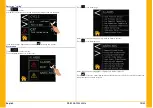
1. switch the power on by turning the MAIN SWITCH “
&
” to “I ON”: the touch is powered.
(for model 325-500)there is a label under the control to informe that:
Y
THE CRANKCASE HEATER MUST BE SWITCHED ON 12 HOURS BEFORE STARTING THE DRYER.
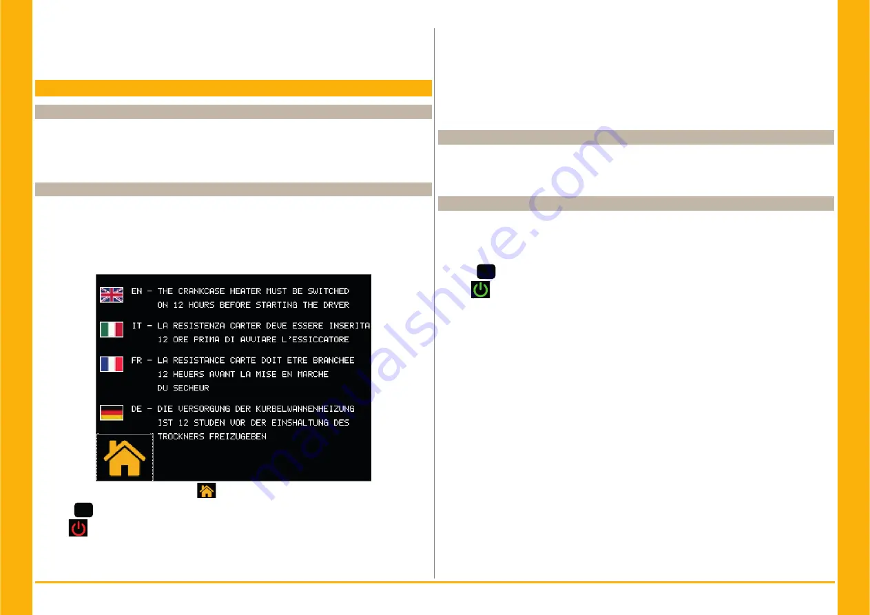
(for model 700-1000) appear on display:
touch
to see home screen
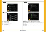
2. Press
set
to start (for model 325-500).
Press
to start (for model 700-1000).
3. Start the dryer before the air compressor;
Y
Fan (Ac version): if connected with the wrong phase sequence they turn in the opposite direc-
tion, with the risk of being damaged (in this case the air exits the dryer cabinet from the condenser
grilles instead from the fan grille - see par. 9.8 (appenix) for correct air fl ow); immediately invert two
phases.
4. Wait 5 minutes, then slowly open the air inlet valve;
5. slowly open the air outlet valve: the dryer is now drying.
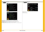
Phases Monitor
If appears to display an alarm, during the start up of the dryer, the user must verify the wiring of the
input terminals of the disconnecting switch of the dryer.
4.3 Operation
• Leave the dryer on during the entire period the air compressor is working;
• The dryer operates in automatic mode, therefore fi eld settings are not required;
• In the event of unforeseen excess air fl ows, by-pass to avoid overloading the dryer.
• Avoid inlet air temperature fl uctuations.
4.4 Stop
1. Stop the dryer 2 minutes after the air compressor stops or in any case after interruption of the air
fl ow;
2. make sure compressed air does not enter the dryer when the dryer is disconnected or if an alarm
occurs.
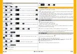
3. Press
set
to stop the dryer (for model 325-500).
Press
to stop the dryer (for model 700-1000).
4. Turn the MAIN SWITCH “
&
” to “O OFF” to switch the power off.
Y
Wc
version, close the water circuit with the dryer stopped.
Summary of Contents for PSE 325
Page 2: ......
Page 76: ...14 PSE 325 1000 60Hz 9 7 REFRIGERANT CIRCUIT PSE325 500 Ac PSE325 500 ...
Page 77: ...15 PSE 325 1000 60Hz REFRIGERANT CIRCUIT PSE700 1000 Ac PSE700 PSE800 PSE1000 ...
Page 78: ...16 PSE 325 1000 60Hz REFRIGERANT CIRCUIT PSE700 1000 Wc PSE700 PSE800 PSE1000 ...
Page 87: ...25 PSE 325 1000 60Hz WIRING DIAGRAM PSE700 1000 Sheet 1 of 10 ...
Page 89: ...27 PSE 325 1000 60Hz WIRING DIAGRAM PSE700 1000 Sheet 3 of 10 700 800 1000 ...
Page 90: ...28 PSE 325 1000 60Hz WIRING DIAGRAM PSE700 1000 Sheet 4 of 10 ...
Page 91: ...29 PSE 325 1000 60Hz WIRING DIAGRAM PSE700 1000 Sheet 5 of 10 ...
Page 92: ...30 PSE 325 1000 60Hz WIRING DIAGRAM PSE700 1000 Sheet 6 of 10 ...
Page 93: ...31 PSE 325 1000 60Hz WIRING DIAGRAM PSE700 1000 Sheet 7 of 10 ...
Page 94: ...32 PSE 325 1000 60Hz WIRING DIAGRAM PSE700 1000 Sheet 8 of 10 ...
Page 95: ...33 PSE 325 1000 60Hz WIRING DIAGRAM PSE700 1000 Sheet 9 of 10 ...
Page 96: ...34 PSE 325 1000 60Hz WIRING DIAGRAM PSE700 1000 Sheet 10 of 10 700 1000 ...
Page 97: ......
Page 98: ......
Page 99: ......


