20
PSVG-IQAN-C2E1M1W1U1
Power
The PVSG-IQAN is powered by a direct battery connection. The gateway
is turned on by applying power to the power control input.
The PVSG-IQAN operates in a 12 V or 24 V system and can operate from
6.5 V up to 32 V with over-voltage protection at 36 V.
Direct Battery Input (+VBATT)
Parameter
Min
Nom
Max
Units
Input voltage for normal operation (see note 1)
6.5
-
32
V
Maximum continuous voltage (see note 2)
-
-
36
V
Maximum peak current (see note 3)
VBATT=6.5 V
VBATT=13.8 V
VBATT=28.0 V
VBATT=32.0 V
3.17
1.50
0.74
0.64
A
A
A
A
Recommended External Fuse
-
3
-
A
Note 1:
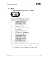
It is strongly recommended that Pin 6 of the module be
connected directly to the vehicle battery source and to utilize Pin 11
(Power Control) for activating and deactivating, as well as allowing a
safe shut-down sequence of, the module. Connecting Pin 6 to a
switched battery source may result in memory corruption which, in its
most severe case, may render the unit inoperable and require device
reprogramming to recover.
Note 2:
Exposure to maximum voltages for extended periods may
affect device reliability.
Note 3:
Maximum peak current is a theoretical calculation assuming
maximum current draw for each peripheral as specified in datasheets,
85% efficiency for step-down regulators, and peak cellular current
during a 1-slot Tx burst at maximum power. Note the burst duration is
typically 1 ms or less, thus not affecting recommended fuse ratings.
5. Power
Summary of Contents for PSVG-IQAN-C2E1M1W1U1
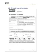
Page 42: ...34 PSVG IQAN C2E1M1W1U1 Markings Approvals 9 3 EU Declaration of conformity...
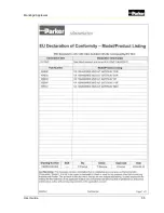
Page 43: ...User Guide 35 Markings Approvals...
Page 47: ......
Page 48: ...HY33 5027 IB US...


