24
PSVG-IQAN-C2E1M1W1U1
Communication
7.1.2. J1939 CAN Installation Connections
The CAN connection for the PVSG-IQAN should conform to the J1939
standard. The J1939 standard is a robust automotive specification that is a
good CAN installation guideline even when the J1939 CAN protocol is not
being used.
For a list of J1939 connection considerations, refer to the SAE J1939
specifications available through the Society for Automotive Engineers.
SAE J1939-11 covers the physical aspects of the CAN bus including cable
type, connector type, and cable lengths.
Note: The standard variant of the PVSG-IQAN
does not have a
CAN termination resistor
, which is based on the assumption
that the CAN bus is terminated in the harness.
The following lists the elements that are required for a J1939 CAN
connection:
CAN Cable: A shielded twisted-pair cable should be used when
connecting multiple modules to the CAN bus. The cable for the J1939
CAN bus has three wires: CAN - High, CAN - Low, and CAN Shield
(which connect to the corresponding CAN_HIGH, CAN_LOW, and
CAN_SHIELD pins on the connector). When a module does not have a
CAN_SHIELD pin, the CAN Shield should be connected to an
available ground terminal attached to the negative battery. The CAN
cable must have an impedance of 120 Ω.
CAN Connectors: Industry-approved CAN connectors are
manufactured by ITT Cannon and Deutsch, and come in either T or Y
configurations.
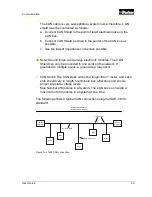
CAN Harness: The CAN harness is the main backbone cable that is
used to connect the CAN network. This cable cannot be longer than 40
meters
and must have a 120 Ω terminating resistor at each end
.
The 120 Ω terminating resistors eliminate bus reflections and ensure
proper idle-state voltage levels.
Summary of Contents for PSVG-IQAN-C2E1M1W1U1
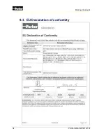
Page 42: ...34 PSVG IQAN C2E1M1W1U1 Markings Approvals 9 3 EU Declaration of conformity...
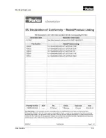
Page 43: ...User Guide 35 Markings Approvals...
Page 47: ......
Page 48: ...HY33 5027 IB US...

