background image

Bulletin MSG30-3254-INST/UK

Installation and setup 

manual

Electro-hydraulic control 

for serie PVplus

Pump design series 44-45-46-47,
compensator design series 45

Effective: July 1st, 2021

Supersedes: March 1st, 2017

Visit our homepage 

for additional support

parker.com/pmde

Summary of Contents for PV Series

Page 1: ...llation and setup manual Electro hydraulic control for serie PVplus Pump design series 44 45 46 47 compensator design series 45 Effective July 1st 2021 Supersedes March 1st 2017 Visit our homepage for additional support parker com pmde ...

Page 2: ... UDK old UPR UPK 6 4 Proportional displacement control with closed loop pressure control code UDM old UPM 8 5 Preload valve for proportional controlled pumps code PVAPVV 10 Table 1 Main dimensions preload manifold 11 6 External pilot pressure supply 12 7 Quick pressure relief with quick unload valve code PVAPSE in combination with controls codes UDS resp UDQ 13 8 Preload and quick unload manifold ...

Page 3: ...B valve with pressure compensation standard design from 07 2015 Code option R pilot operated pressure control NG6 interface K as option R additional proportional pressure valve PVACRE K mounted M as option K additional pressure sensor PVACMS mounted for closed loop pressure control P pilot operated pressure control NG6 interface for pre load and quick unload manifold F as option P for pre load and...

Page 4: ...nic module for a flow command of 100 The spool connects thereby port A with the pump housing Port T The oil out of the large piston area drains off the pump is swashing to maximum displace ment Solenoid B is activated in case of 0 flow command The pump outlet pressure p1 on the large servo piston area downstrokes the pump Figure 2 Circuit diagram FDV control FDV Function to minimum displacement Th...

Page 5: ...18 30 V 0 0 V 9 6 29 31 13 14 11 5 7 8 10 3 17 19 12 15 16 1 2 12 V 5 V DC DC PWM 18 20 21 23 4 22 24 enable ramp 24 V nominal enable p Q control 24 V nominal enable power amplifier 24 V nom connect to terminal 11 0 V displacement transducer LVDT 0 10 V or CIP 4 20 mA pressure command pcmd 0 10 V or 4 20 mA horse power 0 10 V command Lcmd 0 pressure transducer 0 10 V or 4 20 mA displacement cmd Qc...

Page 6: ...or with the displacement control valve Figure 5 show the hydraulic circuit of the UDK option 3 Proportional displacement control with pressure compensation codes UDR UDK old UPR UPK S T MP1 P pA A P T A P T S U P T M WV BP BD2 A P T A P PP T XQ Xp IP IQ A IQ B WQ Wp Displacement control Code PVCMD1FBU Pressure compensator Stage Code PVCM U2 Proportional pressure pilot valve Code PVACRE K not inclu...

Page 7: ...rd remote compensator It is mandatory that the displacement setting of the displacement control stage is high enough to cover the flow requirements of the system the pump and the control valves to maintain the desired pressure The following valve is to be used with this mod ule PVACRE K Other valve models can lead to instability problems or malfunction of the control This valve is designed for a n...

Page 8: ...CMS SCP01 600 24 06 Also included in the shipment is a pro portional pressure pilot valve of the ordering code PVACRE K The hydraulic function is described in the recent chapter There are no differences except the pressure sensor S T MP1 P A P T A P T S U P T WV BP BD2 A P T A P P T P XQ XP IP IQ A IQ B WQ WP Displacement control valve Code PVCMD1FBU Pressure compensator Code PVCM U2 Proportional ...

Page 9: ...r hand there are additional measures necessary e g command signal correction if linearity between input command signal and output system pressure is required Figure 7 shows the typical behaviour of pilot pressure pp and system pressure p1 as function of the input signal The digital control module offers the required signal correction to compensate for this effect The standard module parameter sets...

Page 10: ...d valve The preload valve is offered as a manifold that can directly be flanged to the pressure port of the pump The ordering code is PVAPVV The stands for the frame size of the pump the screw option and the seal material The preload valve is also available as slip in car tridge valve according to DIN 24 342 Because of the pilot valve characteristic the opening pressure p1 is approx 20 bar The por...

Page 11: ...ts according to ISO 6149 Input and output are designed as flange ports according to ISO 6162 and fit direct to the ac cording PV frame size Table 1 shows the main dimensions Figure 9 Outside view of the preload manifold for direct pump mounting Outlet optional to front shaft side or to the rear Table 1 Main dimensions preload manifold dimension BG1 BG2 BG3 BG4 BG5 BG6 H mm 100 100 110 110 120 120 ...

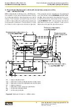
Page 12: ...t Figure 10 shows the hydraulic circuit for this option As long as the pump outlet pressure is lower than the external supply pressure the control circuit is powered by the external source When the system pressure exceeds the auxiliary pressure the control is internally pressurized Please note for pressures below the auxiliary pressure a pressure control is not possible because the control senses ...

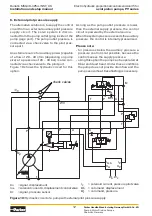
Page 13: ... pump with p Q control and the quick unload valve A 2 way SAE port mounted valve is inserted into the pilot line to the pressure compensator stage The pilot flow to the proportional pressure pilot valvehastopasstwoorificesinthepoppetandin the cover of this valve The poppet is kept closed with a 9 bar spring The pressure compensator stage has in this case not the control spool with the internal pil...

Page 14: ...r codes UDP resp UDF hose to the control ports of this manifold The hydraulic circuit diagram in figure 12 display this Both functions are built into one manifold Figure 13 shows this manifold and table 3 lists the main dimensions The dimension L indicates the total length of the mounting bolts and includes the length screwed into the pump end cover The hydraulic connections between manifold and p...

Page 15: ... covered Figure 13 Preload and quick unload manifold Table 3 Main dimensions of the preload and quick unload manifold dimension BG1 BG2 BG3 BG4 BG5 BG6 B mm 125 150 157 157 190 190 H mm 105 130 130 130 154 154 T mm 80 80 92 92 105 105 L mm 105 103 121 121 137 5 137 5 B1 mm 189 189 196 196 239 239 H1 mm 166 166 166 166 199 199 T1 mm 116 116 137 137 155 155 for size PV016 028 PV032 046 PV063 092 PV1...

Page 16: ...thesettingsaresecured New or readjustment is only necessary after repair or replacement At full stroke the adjustment of the sensor can be verified The current at the CIP output pin 6 at the control module should have a value between 20 20 4 mA Teach Process 1 Solenoidtobeconnectedaccordingtochap ter 9 and 10 to the electronic control module 2 To teach the sensor switch to controller option TYPE S...

Page 17: ... displacement The displacement of the pump can be checked with the help of a flow measuring device The maximum displace ment is reached if the displacement flow does not further increase even when the input command is still raised Figure 15 Hydraulic sheme for pump in 100 displacement 9 Push button on teach adapter for 1 second 100 displacement value is defined 20 mA LED on sensor emits a permanen...

Page 18: ...DT and the solenoid of the displacement control valve are to be connected according to chapter 9 to the electronic control module Size voltage size voltage PV016 6 34 V PV063 7 12 V PV020 6 06 V PV080 6 48 V PV023 5 87 V PV092 6 10 V PV028 5 50 V PV140 5 24 V PV032 6 40 V PV180 3 83 V PV040 5 70 V PV270 4 06 V PV046 5 43 V PV360 4 06 V Protection plug with o seal Zero adjustment sealed Do not touc...

Page 19: ...ty valve This valve has to be layed out for full pump flow The remote pressure compensation stage of the p Q controls codes UDR UDK UDM UDS UDP und UDF old UPR UPK UPM UPS UPQ UPP and UPF refered chapters 2 to 7 is adjusted as follows Differential pressure adjustment Lock nut The factory setting for the differential pressure is 15 1 bar For re adjustment two pressure gages transducers are required...

Page 20: ...A P T A P T S U Cable 1 CIP LVDT Cable 3a Solenoid A Cable 3b Solenoid B displacement control valve Code PVCMD1FBD enable ramp 24 V nominal connect to terminal 11 0 V displacement cmd Qcmd 0 10V or 4 20 mA 0 V displacement transducer LVDT 0 10 V or CIP 4 20 mA 18 30 V 0 18 30 V 0 9 6 29 31 13 14 11 5 7 8 10 3 17 19 12 15 16 1 2 18 20 21 4 22 24 23 12 V 5 V DC DC PWM µC enable power amplifier 24 V ...

Page 21: ...CRE K 18 30 V 0 18 30 V 0 0 V 9 6 29 31 13 14 11 5 7 8 10 3 17 19 12 15 16 1 2 12 V 5 V DC DC PWM 18 20 21 23 4 22 24 µC connect to terminal 11 0 V displacement transducer LVDT 0 10 V or CIP 4 20 mA pressure command pcmd 0 10 V or 4 20 mA horse power 0 10 V command Lcmd 0 pressure transducer 0 10 V or 4 20 mA displacement cmd Qcmd 0 10 V or 4 20 mA enable ramp 24 V nominal enable p Q control 24 V ...

Page 22: ...ve shielded cable with molded connector in different length and variations cable 4 x 0 5 mm shielded max 50 m long connector CIP round type M12 x 1 4 pin LVDT round type M12 x 1 5 pin angled version protection class IP 65 for voltages up to 250 V CIP PQ module control Pin 6 24 V Teach in Pin 9 PQ module control LVDT cable 3 a b 3 x 0 5 mm shielded max 50 m long connector according DIN 43 650 versi...

Page 23: ...d FPV UPR UPP UPS cable 3 x 1 5 mm max 50 m long connector according DIN 43 650 version AF 3 pin protection class IP 65 for voltages up to 250 V PIN 20 solenoid A PIN 23 solenoid B PIN 18 solenoid A PIN 21 solenoid B cable 3 a b 3 x 1 5 mm max 50 m long connector according DIN 43 650 version AF 3 PIN protection class IP 65 for voltages up to 250V Cable 3 a b to displacement control valve displacem...

Page 24: ...mp turns reason solution Wrong direction of rotation Change direction of motor rotation reason solution Fluid reservoir empty or not filled to level suction line ends above fluid level Fille reservoir to required level if necessary increase suction pipe length reason solution Suction line is blocked E g by plugs cleaning tissues plastic plugs Ball valve in the suction line closed Suction filter bl...

Page 25: ...alve is blocked Connect pressure pilot valve to compensator make sure valve opens as required reason solution No or too low pressure at pump outlet port Pump outlet pressure must be at least 15 bar because otherwise the bias spring in the pump cannot be compressed Pump does not upstroke sticks at zero displacement reason solution Compensator is blocked due to contamination Clean hydraulic fluid cl...

Page 26: ...nufacturing Germany GmbH Co KG Pump Motor Division Europe Chemnitz Germany Electro hydraulic proportional controls version 45 for axial piston pumps PV series Bulletin MSG30 3254 INST UK Installation and setup manual Notes ...

Page 27: ...nufacturing Germany GmbH Co KG Pump Motor Division Europe Chemnitz Germany Electro hydraulic proportional controls version 45 for axial piston pumps PV series Bulletin MSG30 3254 INST UK Installation and setup manual Notes ...

Page 28: ...eeable uses of the components or systems Offer of Sale Please contact your Parker representation for a detailed Offer of Sale WARNING USER RESPONSIBILITY Position notification regarding Machinery Directive 2006 42 EC Products made by the Pump Motor Division Europe PMDE of Parker Hannifin are excluded from the scope of the machinery directive following the Cetop Position Paper on the implementation...

Reviews: