31
Gateway Connections (Pinout)
4.1.3.
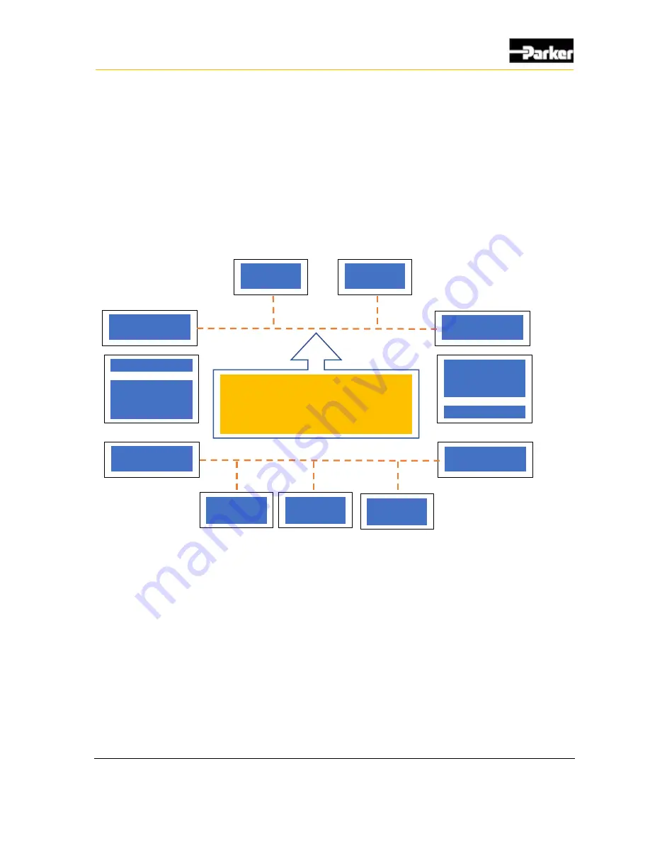
CANBUS Module Block Diagram
When utilizing the PVSG-IQAN gateway with an IQAN based control system, it is
very important to connect the diagnostic bus of the gateway to the diagnostic bus
of the IQAN Master Controller. See Figure 15.
Figure 16. Block diagram of wiring PVSG-IQAN Gateway
IQAN Master
Controller
IQAN Master
Controller
Diagnostics Bus-
CAN1/CANB
Diagnostics Bus-
CAN0/CANA
PVSG -IQAN
Gateway
Diagnostics Bus-
(configurable)
Other CAN Bus-
Configurable
IQAN Master
Controller
(Headmaster)
I/O Modules
Transmission
Engine
Diagnostics CANBUS must be
connected between master module
and gateway to use - IQAN telematics
signals
Summary of Contents for PVSG-IQAN-C2E1M2W1U1
Page 23: ...14 Quick Start Guide Figure 6 Create New Users Steps...
Page 26: ...17 Quick Start Guide Figure 8 Create New Organizations Steps...
Page 62: ...53 Markings Approvals 9 4 EU Declaration of conformity NA Gateway...
Page 63: ...54 Markings Approvals...
Page 64: ...55 Markings Approvals 9 5 EU Declaration of conformity EU Gateway...
Page 65: ...56 Markings Approvals...
Page 66: ...57 Appendix 10 Appendix...
Page 69: ...60 Appendix Symbol Meaning Battery Fuse Resistor Ground Chassis ground...
Page 70: ...HY33 5027 IB US...


