background image

Variable displacement pump

Series VP1-045 / -075

Bulletin HY30-8222-INST/UK

Installation information

3

Parker Hannifin

Pump & Motor Division Europe

Trollhättan, Sweden

The VP1 input shaft must 

not

 be subject to 

external radial and/or axial forces (see 
illustration to the right).

Installation examples:

a)

   A gear drive with a bearing supported 

gear is acceptable (as shown in the illus-
tration below)

b)

   A gear mounted directly on the VP1 input 

shaft is usually 

not

 acceptable

c)

   A belt drive pulley installed directly on 

the VP1 input shaft is usually 

not

 allowed 

Fig. 3.  Usually, no external radial and/or 

axial forces are allowed on the VP1 shaft

VP1 installation on a PTO /engine PTO

NOTE

 If an installation according to  
b) or c) above, is considered, 
contact Parker Hannifin.

VP1_to_PTO_install_09-02-12.ai

Leif A.

Fig. 4. VP1-045/075 shown with a bearing supported gear on an engine PTO adapter 

(example).

VP1-045/075_no_shaft_loads.ai
Leif A./11-02-04

Summary of Contents for Series VP1-045/-075

Page 1: ...ulletin HY30 8222 INST UK Installation and Startup Manual Hydraulic Pumps SeriesVP1 045 075 Effective September 01 2016 Supersedes August 25 2011 Visit our homepage for additional support parker com pmde ...

Page 2: ...ct the drain line directly to the oil cooler if the hydraulic system is so equipped 6 A pressure relief valve is recommended in the outlet pressure line from the pump it should be set 15 20 bar higher than max pressure setting of the pump Example The main pressure relief valve located in the direc tional control valve 7 Fill the pump with oil and bleed the pump before start up NOTE The suction fit...

Page 3: ... the illus tration below b A gear mounted directly on the VP1 input shaft is usually not acceptable c A belt drive pulley installed directly on the VP1 input shaft is usually not allowed Fig 3 Usually no external radial and or axial forces are allowed on the VP1 shaft VP1 installation on a PTO engine PTO NOTE If an installation according to b or c above is considered contact Parker Hannifin VP1_to...

Page 4: ...tallation on an engine PTO BPV VP1 unloading valve The BPV VP1 unloading valve is utilized in hydraulic systems where the pump is in constant operation The valve protects the pump from being overheated in the off load mode by allow ing a small flow through the pump When load sensing valve function is engaged the bypass flow is cut off as port X is being pressurized The valve will also de air the s...

Page 5: ... line is required between control port T and the reservoir fig 6 Do not install a suction filter in the inlet line Fluids Suitable fluids Mineral based hydraulic flu ids type HLP DIN 51524 ATF automatic transmission fluids and API CD motor oils Fluid temperature Main circuit Max 75 C Viscosity Recommended viscosity 20 30 mm2 s cSt Operating viscosity limits Min 10 mm2 s max 400 mm2 s At start up m...

Page 6: ...ched to the gearbox it must not be fastened to the truck chassis Likewise when the tandem assembly is installed on a separate bracket and driven by a cardan shaft the auxiliary pump should have a support attached to the pump bracket Fig 7 Adaptor kit P N 379 7795 for tandem coupling IMPORTANT Contact Parker Hannifin for additional information when considering tandem mounting a second VP1 pump Inst...

Page 7: ...e be set higher than 380 bar when the hydraulic system is being delivered to a customer Make sure max pressure not exceed 400 bar The pressure can easily be measured in the gauge port on the pump housing Differential pressure setting The standby pressure p is factory set at 25 bar but is adjustable to 35 bar This 25 bar setting and the installed standard orifices usually provide an acceptable dire...

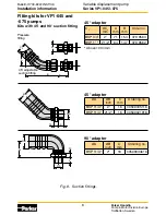
Page 8: ...379 9562 Above 100 l min Fig 9 Suction fittings C2 C2 C2 C1 C1 C1 Fittings_install_GB eps Leif A 020115 A B A B Pressure fitting 45 adjustable suction fitting Fitting kits for VP1 045 and 075 pumps Kits with 45 and 90 suction fitting Nipplar_ny eps Leif A 05 01 21 13 C ØA ØB ØB ØA 44 13 C 45 adapter ØA ØB inch C mm Ordering no BSP 11 4 2 18 00509035116 BSP 11 4 21 2 18 00509021916 90 adapter ØA ØB...

Page 9: ... indication hole on the pump Stop the system immediately Determine the cause of leakage Replace damaged parts Make sure you have corrected the source of the problem not only the symptom Parker can not be held responsible for damage to PTO engine and gear box caused by improper maintenance of the hydraulic system V P 1 4 5 7 5 c r o s s s e c t i o n L e i f A 0 2 0 1 1 5 Fig 10 Indication hole ...

Page 10: ...he Fluid Power Industry All PMDE products are designed and manufactured considering the basic as well as the proven safety principles according to SS EN ISO13849 2 2008 09 C 2 and C 3 and SS EN 982 A1 2008 so that the machines in which the products are incorporated meet the essential health and safety requirements Confirmations for components to be proven component e g for validation of hydraulic ...

Page 11: ...nts and assuring that all performance endurance maintenance safety and warning requirements of the application are met The user must analyze all aspects of the application follow applicable industry standards and follow the information concerning the product in the current product catalog and in any other materials provided from Parker or its subsidiaries or authorized distributors To the extent t...

Page 12: ...NST UK Pump Motor Division Europe Art No 3780474 09 461 82 Trollhättan Sweden Copyright 2016 Tel 46 0 520 40 45 00 All rights reserved www parker com pmde Variable displacement pump Series VP1 045 075 Bulletin HY30 8222 INST UK Installation information ...

Reviews: