ENGLISH
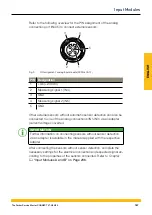
Refer to the following overview for the PIN assignment:
3
4
5
1
2
Fig. 11
PIN assignment, CAN input module (SCMI-600-02)
PIN Designation
1
Shielding
2
Not connected
3
GND
4
CAN High
5
CAN Low
After connecting the sensors without sensor detection, complete the
necessary settings for the electrical connection and expected signal ac-
cording to the properties of the sensors connected. Refer to Chapter
&
"Input Modules A and B" on Page 236
169
The Parker Service Master CONNECT V1.0/04/20
Input Modules
Summary of Contents for Service Master CONNECT
Page 1: ...The Parker Service Master CONNECT Bedienungsanleitung Operating Manual ...
Page 107: ...DEUTSCH Abb 55 Gerät Device 107 The Parker Service Master CONNECT V1 0 04 20 Bedienung ...
Page 133: ...DEUTSCH 12 3 Maßzeichnungen 133 The Parker Service Master CONNECT V1 0 04 20 Anhang ...
Page 134: ...DEUTSCH 134 The Parker Service Master CONNECT V1 0 04 20 Anhang ...
Page 135: ...DEUTSCH 135 The Parker Service Master CONNECT V1 0 04 20 Anhang ...
Page 137: ...DEUTSCH 137 The Parker Service Master CONNECT V1 0 04 20 Anhang ...
Page 245: ...ENGLISH Fig 55 Device 245 The Parker Service Master CONNECT V1 0 04 20 Operation ...
Page 271: ...ENGLISH 12 3 Dimensional Drawings 271 The Parker Service Master CONNECT V1 0 04 20 Appendix ...
Page 272: ...ENGLISH 272 The Parker Service Master CONNECT V1 0 04 20 Appendix ...
Page 273: ...ENGLISH 273 The Parker Service Master CONNECT V1 0 04 20 Appendix ...
Page 275: ...ENGLISH 275 The Parker Service Master CONNECT V1 0 04 20 Appendix ...


