ENGLISH
6.5.4 Trigger
The
Trigger
measuring method starts recording of the measured val-
ues through the triggering of a defined trigger.
Recording is stopped automatically after the defined storage time has
expired.
After selecting the
Trigger
measuring method, the device displays a
predefined trigger and corresponding parameters to complete the mea-
surement.
1
Tap on the
button.
Ä
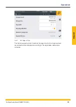
The configuration window opens in which to define the param-
eters.
2
Define the parameters and select a trigger according to your ap-
plication.
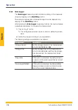
The following parameters are available:
Designation
Description
Storage interval
Set the storage interval of the measurement in
the format
h : m : s : ms
Storage time
Set the storage time for the measurement in
the format
d : h : m : s
When the storage time
has expired, the measurement stops automati-
cally
Recording MIN/MAX If this option is activated, the Min and Max
measured values are also recorded in addition
to the current measured value
Pre-Trigger time
Define the period of time in which the mea-
sured values have already been recorded prior
to the trigger being triggered
Trigger type
Select the trigger type for the measurement
Auto repeat
When the option is activated, the measurement
is started again the next time the trigger is trig-
gered after automatic storage of the previous
measurement
Ring buffer
If this option is activated, the defined memory
area is continuously overwritten by current
measured data
210
The Parker Service Master CONNECT V1.0/04/20
Operation
Summary of Contents for Service Master CONNECT
Page 1: ...The Parker Service Master CONNECT Bedienungsanleitung Operating Manual ...
Page 107: ...DEUTSCH Abb 55 Gerät Device 107 The Parker Service Master CONNECT V1 0 04 20 Bedienung ...
Page 133: ...DEUTSCH 12 3 Maßzeichnungen 133 The Parker Service Master CONNECT V1 0 04 20 Anhang ...
Page 134: ...DEUTSCH 134 The Parker Service Master CONNECT V1 0 04 20 Anhang ...
Page 135: ...DEUTSCH 135 The Parker Service Master CONNECT V1 0 04 20 Anhang ...
Page 137: ...DEUTSCH 137 The Parker Service Master CONNECT V1 0 04 20 Anhang ...
Page 245: ...ENGLISH Fig 55 Device 245 The Parker Service Master CONNECT V1 0 04 20 Operation ...
Page 271: ...ENGLISH 12 3 Dimensional Drawings 271 The Parker Service Master CONNECT V1 0 04 20 Appendix ...
Page 272: ...ENGLISH 272 The Parker Service Master CONNECT V1 0 04 20 Appendix ...
Page 273: ...ENGLISH 273 The Parker Service Master CONNECT V1 0 04 20 Appendix ...
Page 275: ...ENGLISH 275 The Parker Service Master CONNECT V1 0 04 20 Appendix ...


