22
Prior to unit start-up, all installation set-up instructions
must be completed as specified by this manual. Refer
to Section 3.
4.1 Start-Up
Inspect the installation area and make certain no tools, parts, etc.,
have been left on or inside the SFC unit. Check blower discharge to
make certain it is free from all debris.
Start motor/blower and check for proper rotation. A rotation arrow
is located on the blower housing. All top-mount blower assemblies
rotate in a clockwise rotation as viewed from the driven end (motor
end with motor cooling fan). If blower is rotating in the opposite direc-
tion, place disconnect switch in the OFF position to the motor starter.
For 3-phase blowers, interchange any two power wires to the motor
at the load side of the motor starter contactor. For single-phase
power, refer to motor nameplate for which two wires to interchange
at motor junction box. Engage starter disconnect switch, start blower
and recheck rotation.
NOTE: Proper blower rotation is required to move the designed
amount of air. A blower rotating in the incorrect direction will
only move approximately 40% of design airflow.
The blower assembly provided by Parker includes an
outlet damper. If the blower assembly was purchased
separately, ensure an outlet damper is included. Close
the blower discharge damper to the 50% open posi-
tion and tighten in place. If a volume control damper is
provided in another part of the dust collection system,
adjust second damper to the 50% open position and
tighten in place.
NOTE: It is important that the air volume of the dust collection
system is at design conditions at system start-up. There is
a minimal pressure differential across new cartridge filters.
If the volume control damper is not correctly adjusted,
the air volume will be above design conditions for airflow
and will affect cartridge filter life and may kick-out starter
overloads.
!
CAUTION
CAUTION
Summary of Contents for SFC
Page 1: ...Downward Flow Cartridge Dust Collector Owner s Manual Model SFC...
Page 7: ...v Page intentionally left blank...
Page 11: ...4 FIGURE 2 SFC Typical SINGLE UNIT Installation Diagram PARKER PARKER 44 10335 0001...
Page 12: ...5 FIGURE 3 Recommended Unit Clearances 44 10337 0001...
Page 14: ...7 FIGURE 4 Single Hopper SFC 44 10309 0001...
Page 15: ...8 FIGURE 5 Multiple Hopper SFC 44 10309 0002...
Page 16: ...9 FIGURE 6 Multiple Hopper SFC 44 10309 0003...
Page 17: ...10 FIGURE 7 Multiple Modules SFC 44 10310 0001...
Page 19: ...12 FIGURE 8 SFC Pressure Gauge Installation 44 10333 0001 Rev A...
Page 20: ...13 FIGURE 9 Solenoid Wiring to Pulse Controls for 2 3 4 and 5 Tier Units...
Page 21: ...14 FIGURE 10 Pneumatic Valve Assembly 44 10332 0001...
Page 24: ...17 FIGURE 12 Abrasive Inlet Installation 44 10338 0001...
Page 27: ...20 FIGURE 16 EDAP Interconnection FIGURE 15 EDAP Installation 48 10007...
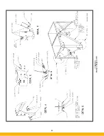
Page 30: ...23 FIGURE 17 SFC Series Door Filter Installation 44 10329 0001...
Page 37: ...30 7 Illustrated Parts FIGURE 21 SFC Series 44 10330 0001 FIGURE 22 SFC Series Explosion Vents...


