i
i
Page
Safety Precautions
...................................................................................................iii
1. Important Notice
................................................................................................1
2. Introduction
........................................................................................................1
2.1 Unit Nomenclature .........................................................................................1
2.2 Description and Operation .............................................................................1
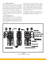
2.3 Air Filtering Operation .....................................................................................2
2.4 Filter Cleaning Cycle .......................................................................................2
3. Installation
..........................................................................................................3
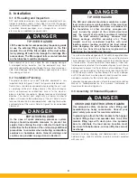
3.1 Off Loading and Inspection ............................................................................3
3.2 Installation Planning........................................................................................3
3.3 Assembly of Standard Equipment ..................................................................3
3.3.1 Hopper Assemblies ...............................................................................6
3.3.2 Fully Assembled Filter Module Sections .......................................................6
3.3.3 Multiple, Bolt-Together Module Sections
(applies to 4 or more modules) ..............................................................6
3.4 Electrical Installation .....................................................................................11
3.4.1 Mounting the Controls .........................................................................11
3.4.2 Solenoid Valve Enclosure Wiring ..........................................................11
3.4.3 Heater Wiring ......................................................................................15
3.5 Compressed Air Connection ........................................................................15
3.6 Assembly of Optional Equipment .................................................................15
3.6.1 Blower Package Installation .................................................................15
3.6.2 Duct Silencer Installation ......................................................................18
3.6.3 Rotary Air Lock Installation ..................................................................18
3.6.4 Abrasive Inlet Installation ......................................................................18
3.6.5 Drum Lid Installation ............................................................................18
3.6.6 Inlet Cover and Blank Cover Plate Installation ......................................19
3.6.7 Remote Blower Start/Stop Assembly ..................................................19
3.6.8 Explosion Vents ...................................................................................21
3.6.9 Extend Dirty Air Plenum (EDAP) for 5 high units ...................................21
Summary of Contents for SFC
Page 1: ...Downward Flow Cartridge Dust Collector Owner s Manual Model SFC...
Page 7: ...v Page intentionally left blank...
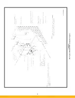
Page 11: ...4 FIGURE 2 SFC Typical SINGLE UNIT Installation Diagram PARKER PARKER 44 10335 0001...
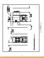
Page 12: ...5 FIGURE 3 Recommended Unit Clearances 44 10337 0001...
Page 14: ...7 FIGURE 4 Single Hopper SFC 44 10309 0001...
Page 15: ...8 FIGURE 5 Multiple Hopper SFC 44 10309 0002...
Page 16: ...9 FIGURE 6 Multiple Hopper SFC 44 10309 0003...
Page 17: ...10 FIGURE 7 Multiple Modules SFC 44 10310 0001...
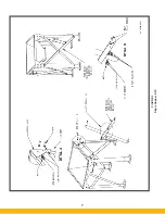
Page 19: ...12 FIGURE 8 SFC Pressure Gauge Installation 44 10333 0001 Rev A...
Page 20: ...13 FIGURE 9 Solenoid Wiring to Pulse Controls for 2 3 4 and 5 Tier Units...
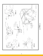
Page 21: ...14 FIGURE 10 Pneumatic Valve Assembly 44 10332 0001...
Page 24: ...17 FIGURE 12 Abrasive Inlet Installation 44 10338 0001...
Page 27: ...20 FIGURE 16 EDAP Interconnection FIGURE 15 EDAP Installation 48 10007...
Page 30: ...23 FIGURE 17 SFC Series Door Filter Installation 44 10329 0001...
Page 37: ...30 7 Illustrated Parts FIGURE 21 SFC Series 44 10330 0001 FIGURE 22 SFC Series Explosion Vents...


