2
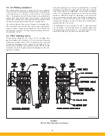
2.3 Air Filtering Operation
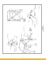
The contaminated airstream is drawn into the dust collector
where its velocity is reduced by inlet baffle plates to provide even
air distribution across the entire surface area of the cartridge
filters. This design enhances filtration efficiency by establishing a
uniform “dust cake” on the filters. The airstream is then directed
around the cartridge filters and down toward the hopper, where
the heavier particles discharge to the dust storage drum.
The contaminated air then passes through the cartridge filters.
The filter media strips the dust from the airstream, allowing only
clean air to pass through the cartridge filter. The air then passes
into the clean air plenum, through a blower package and is dis-
charged from the unit.
2.4 Filter Cleaning Cycle
During normal operation, the surface of the cartridge filters
become loaded with contaminants. The reverse-pulse cleaning
mechanism provides brief bursts of compressed air, directed
through the diaphragm valves, toward the cartridge filter. This
pulsing action dislodges the collected particles from the media,
where they fall into the hopper and are discharged to a dust stor-
age drum or drawer.
During the cleaning cycle, each pair of cartridge filters is cleaned
individually. The solid-state sequential timer actuates a solenoid
valve, which allows an air diaphragm valve to open for approxi-
mately 100 milliseconds. High-pressure air from the air manifold
reservoir is directed through the diaphragm valve toward the
venturi mounted on the tubesheet in front of the cartridge filters.
The venturi, in conjunction with the DIF nozzle, maximizes the
compressed air energy to maximize the amount of collected dust
released from the filter surface.
The dislodged dust removed from the filter is swept downward
into the hopper. The remaining filters are cleaned sequentially.
The sequencing is factory preset at 10-second intervals and is
adjustable to adapt to your particular cleaning needs.
FIGURE 1
SFC Air Filter Operation & Cleaning
44-10334-0001
Summary of Contents for SFC
Page 1: ...Downward Flow Cartridge Dust Collector Owner s Manual Model SFC...
Page 7: ...v Page intentionally left blank...
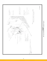
Page 11: ...4 FIGURE 2 SFC Typical SINGLE UNIT Installation Diagram PARKER PARKER 44 10335 0001...
Page 12: ...5 FIGURE 3 Recommended Unit Clearances 44 10337 0001...
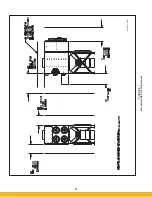
Page 14: ...7 FIGURE 4 Single Hopper SFC 44 10309 0001...
Page 15: ...8 FIGURE 5 Multiple Hopper SFC 44 10309 0002...
Page 16: ...9 FIGURE 6 Multiple Hopper SFC 44 10309 0003...
Page 17: ...10 FIGURE 7 Multiple Modules SFC 44 10310 0001...
Page 19: ...12 FIGURE 8 SFC Pressure Gauge Installation 44 10333 0001 Rev A...
Page 20: ...13 FIGURE 9 Solenoid Wiring to Pulse Controls for 2 3 4 and 5 Tier Units...
Page 21: ...14 FIGURE 10 Pneumatic Valve Assembly 44 10332 0001...
Page 24: ...17 FIGURE 12 Abrasive Inlet Installation 44 10338 0001...
Page 27: ...20 FIGURE 16 EDAP Interconnection FIGURE 15 EDAP Installation 48 10007...
Page 30: ...23 FIGURE 17 SFC Series Door Filter Installation 44 10329 0001...
Page 37: ...30 7 Illustrated Parts FIGURE 21 SFC Series 44 10330 0001 FIGURE 22 SFC Series Explosion Vents...


