Parker Hannifin S.p.A S.B.C. Division
SLVDN User’s Manual
Page 103 of 181
10.7.1.
Positionator
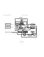
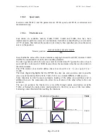
This is a trapezoidal profile generator, with the following user-definable parameters:
speed profile
acceleration and deceleration ramp
value target position in motor step
The parameter referred to the target position is absolute. The difference between the target
position and the reference position, generates the direction of the movement.
The thus position reference generated in this way is loaded into the position loop by
b181.15=0 command, and moreover is possible to unload the reference of the positioning to
the inside of the cam generators through algebraic sum with the reference of the master, with
the selection command b150.3.
Pay attention if both commands (b150.3=1 and b181.15=0), because the reference of the
positioning is used two times:
algebraic sum to the reference of the master in input to two generators CAM1 and CAM2, and
sum in outpu to the references of CAM1 and CAM2.
Activating the command b181.10=1 is possible to unload the reference generated from the
positioning in the global counter position (Pr131:130).
10.7.2.
CAM1 and CAM2
The two CAM generators are specifically designed to meet the requirements of automatic
machines using electronic cams. Four tables are available, namely TAB0, TAB1, TAB2 and
TAB3, that have been implemented to perform a series of cam functions. A vector made of
257 elements describes each table, that indicate the position to be taken by the controlled axis
when the motor axis is in the position:
256
modul
master
number
element
position
Master
•
=
In each table the value of the vector elements is ranging between 0 and 9999, whereas 10,000
shall be the count number set in the slave module parameter.
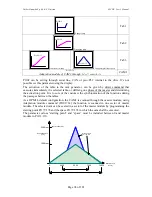
In order to generate a table, the axis route must be divided into 256 points; the value of each
point will have to be rated to 10000, because this is the maximum value that can be written in
the table elements.
The 257th element of each table defines the cam as closed if it is = 0, or as open if it is =
10,000.
The cams will be able to perform the points listed in the table; if the required speed and
torque are within the motor’s electric limits (Maximum Speed and Torque).
Through a series of parameters it is possible to automatically program one of the motion laws
that have been set in the drive in one of the four tables. Functions can be retrieved as follows:

