Parker Hannifin S.p.A S.B.C. Division
SLVDN User’s Manual
Page 130 of 181
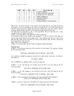
[CMD6] = is the change bit message of a byte parameter. The message has the following
format:
[STX] [110+ADDR] [BK+LUN] [PAR] [D0] [D1] [CHK]
In this case LUN=2 or else two bytes are sent for the data. The first byte is the mask
containing the 0s in the positions of the bits to be changed and 1s in the other positions, while
the second byte contains 1s in the positions of the bits that are to be set to 1 and 0s in the
other positions. The PAR address is that of the parameter (byte) where one or more bits are to
be modified. If the parameter is a word and the bit to be modified is one of the first 8
(b0...b7): PAR = the parameter address; otherwise, if the bit to be modified is one of the
upper 8 (b8...b15): PAR = the address par 1.
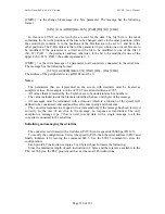
[CMD7] = is the write message of a parameter to all converters connected to the serial line.
The message has the following format:
[STX] [11100000] [BK+LUN] [PAR] [D0]... [Dn] [CHK]
The address of the peripheral device (ADDR) must be 0.
Notes:
- The parameters that are represented on the screen with decimals must be treated as
complete values. For example, a value of 978.5 is read and written as 9785.
- All values that are receded by the $ symbol are to be understood as hex numbers.
- The value included inside the brackets identifies the base unit (byte) of the message.
- All messages must be terminated with a time-out which is a function of the speed, well
defined to be considered valid and must have the exact parity and checksum.
- The converter responds to a request or to a data send only if the message has been received
correctly. In the case of an error in the message, no response is transmitted. The only
exception is message type 7 that is used to send data with a single message to all the
converters connected to the serial line.
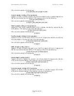
Initializing and managing the serial line
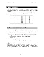
The converter is delivered with a 0 address (Pr27=0) and a speed of 9600 bps (Pr26=5).
To modify the configuration, first set the speed in Pr26, then the serial address in Pr27 and
finally initialise it by issuing the command b42.3. Use the b99.15 command to store the
configuration.
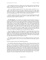
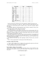
Each pico-PLC instruction occupies 2 or 4 bytes whose format is the following:
Since the maximum length of each instruction in 2 bytes and the total area available in the
PLC is 256 bytes, the PLC program can have at the most 128 instructions.


