


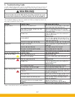
7
The supply voltage and FLA will be noted on the nameplate. The
blower and pulse cleaning system controls are factory pre-wired
for operation. The touchscreen controls are also pre-wired for the
integral option, but require field wiring and connections for the
remote display enclosure option. Wiring diagrams for the various
SHM controls, blower arrangement and supply voltage options are
available within the appendix of this manual. Note that the SHM
does not contain the main disconnect or fuses for the supply power.
Electrical installation should be completed by a qualified professional
and done in accordance with all applicable codes and regulations.
Power cord and connection into unit will be supplied by the cus-
tomer.
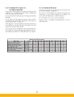
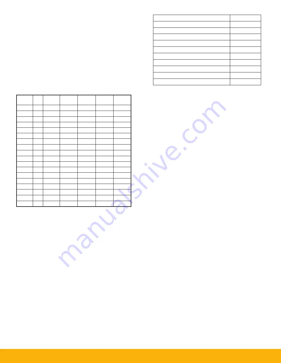
Unit is available in the voltages shown below:
TABLE 1
SHM Voltage and Full Load Amps
Note: When making the main power connections to the unit,
fan rotation check is not required.
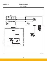
3.5.1 Electrical Power Supply
The main power supply is connected to the SHM unit through a 1˝
FNPT coupling located on the rear of the unit shown in Figure 1B.
After feeding wires through the coupling, terminations are made on
the main bus bar terminal for each phase and frame ground con-
nection. The rear electrical panel also contains the unit circuit break-
ers and DC power supply for the controls components. Utilize Table
1 for wire, fuse and disconnect sizing for your respective product
model. A second plugged 1˝ FNPT coupling is also located on the
rear of the cabinet for low optional voltage connections using the
Machine Interlock feature to automate operation. Ensure that the
rear electrical panel cover is in place and secured prior to operating
the unit. Refer to the electrical wiring diagrams in Table 2 for addi-
tional wiring information.
3.5.2 Electrical Basic Controls
The basic electrical controls consist of a thermal motor protec-
tion disconnect on the side of the unit. This is set for the FLA of
the single blower motor. This is factory prewired to the blower
motor. When installing this unit in the field the customer will con-
nect their factory power to the disconnect on the line side of the
thermal protector. The disconnect On/Off will supply power to
the unit and allow the blower On/Off switch on the front of the
unit to control the blower. Inside the door on the front of the unit
there is a blower speed adjustment. This will control the speed
of the blower from off to full speed. This should be adjusted by
the customer to meet their process requirements.
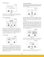
3.5.3 Electrical Touchscreen Controls
The main control panel for the SHM unit is a touchscreen interface
located integrally on the front of the unit or remotely in an auxiliary
enclosure (refer to section 3.5.4) that operates the blower.
The touchscreen control panel is powered by 24V DC. Refer to
Section 4 of this manual for operation of the touchscreen. All wir-
ing in the touchscreen controls panel is pre-wired at the factory
and there are no customer connections at this panel. The panel
door should remain closed and locked during operation.
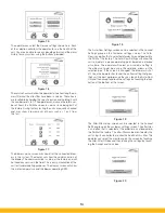
3.5.4 Electrical Remote Panel Controls
Both the Basic and Touchscreen Controls can be mounted
remotely from the unit. The max distance is 100 FT (30.5 m).
The controls are provided in a NEMA 4X enclosure for mounting.
VOLT
PH
#
BLWR
HZ
RPM
FLA
XFMR
208
3
1
50-60
3370
6.5
---
230
3
1
50-60
3370
5.7
---
240
3
1
50-60
3370
5.5
---
380
3
1
50-60
4200
6.7
---
480
3
1
50-60
4200
5.5
---
575
3
1
50-60
4200
---
6kVA
208
3
2
50-60
3370
13.5
---
230
3
2
50-60
3370
11.5
---
240
3
2
50-60
3370
11.0
---
380
3
2
50-60
4200
13.9
---
480
3
2
50-60
4200
11.0
---
575
3
2
50-60
4200
---
10kVA
208
3
3
50-60
3370
18.9
---
230
3
3
50-60
3370
16.4
---
240
3
3
50-60
3370
15.5
---
380
3
3
50-60
4200
19.1
---
480
3
3
50-60
4200
15.5
---
575
3
3
50-60
4200
---
15kVA
FOR BASIC CONTROLS ON SHM-11, SUBTRACT
0.5 AMP FROM FLA VALUES ABOVE.
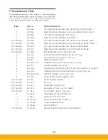
Descripon of Wire Diagram
Appendix
Basic Controls
A1
Remote Panel Basic Controls
A2
One Blower & Controls
A3
Two Blower & Controls
A4
Three Blower & Controls
A5
Remote Panel Touch Controls
A6
One Blower & Remote Controls
A7
Two Blower & Remote Controls
A8
Three Blower & Remote Controls
A9
Transformer 575:480
A10
TABLE 2
Wire Diagrams
Summary of Contents for SmogHog SHM-C
Page 1: ...SMOG HOG Media Mist Collector Owner s Manual Models SHM C SHM F...
Page 6: ...Page intentionally left blank...
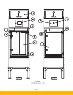
Page 8: ...4 FIGURE 1B SHM Equipment Description 61 10113 FIGURE 1A SHM Equipment Description...
Page 13: ...9 61 10126 FIGURE 4 Remote Panel Touchscreen Connection...
Page 23: ...19 Figure 6 SHM Replacement Parts SHM 11C SHM 11F...
Page 24: ...20 APPENDIX A1 WIRING DIAGRAMS BASIC CONTROLS 04 001682...
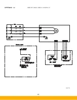
Page 25: ...21 REMOTE PANEL BASIC CONTROLS 04 001799 APPENDIX A2...
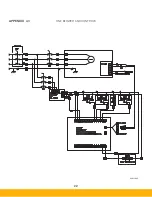
Page 26: ...22 ONE BLOWER AND CONTROLS 04 001695 APPENDIX A3...
Page 27: ...23 TWO BLOWER AND CONTROLS 04 001696 APPENDIX A4...
Page 28: ...24 THREE BLOWER AND CONTROLS 04 001697 APPENDIX A5...
Page 29: ...25 REMOTE PANEL TOUCH CONTROLS 04 001802 APPENDIX A6...
Page 30: ...26 ONE BLOWER AND REMOTE CONTROLS 04 001798 APPENDIX A7...
Page 31: ...27 TWO BLOWER AND REMOTE CONTROLS 04 001797 APPENDIX A8...
Page 32: ...28 THREE BLOWER AND REMOTE CONTROLS 04 001796 APPENDIX A9...
Page 33: ...29 575 480 TRANSFORMER 04 001717 APPENDIX A10...
Page 36: ...32...
Page 37: ...33...


