10
4. Unit Operation
4.1 Start-up
Before system start-up, verify that the installation is complete
per Section 3 of this manual. The following are the basic steps to
walk you through as you are starting up.
1. Open the SHM filter access doors and verify that the filters are in
place and properly sealed.
2. Close and latch all access doors and electrical enclosures on
the unit.
3. Ensure that the main power is connected and turned on.
4. Ensure that all circuit breakers are switched on.
5. Follow Section 4.3 for setting changes on the touchscreen to
target the desired airflow volume. Adjust the blower speed to the
RPM % that will provide the targeted airflow. For assistance in
determining the target RPM, contact your local representative.
When using the Auto Flow option, follow the Auto Flow Settings in
Section 4.
6. Press the blower power button on the Home screen to begin
operation. Note that if the oil mist collector is connected to a
process, other equipment will need to be engaged as well.
7. Verify performance of the system by measuring airflow or evaluat-
ing capture at each collection point. It is recommended to record
baseline performance parameters so the system can be reset in
case of an upset condition or system change. The recorded data
should include:
• the static pressure at each collection hood
• system amperage draw and filter pressure drop at a minimum
• any other key pieces of data critical to your process.
8. To optimize system performance and extend filter life, run the unit
at the minimum airflow required to control the process.
4.2 System Operation
As the SHM collects contaminate, a layer builds up on the outside
surface, causing an increased pressure drop through the filters.
As the differential pressure rises, the blower RPM will need to be
increased in order to maintain the desired airflow. When the filters
are saturated, the contaminant drips to the bottom of the unit and
collects within the oil sump where it can be drained and disposed
of. When the system can no longer generate the airflow required
to capture or convey the collected contaminate, the filters must be
replaced.
4.2.1 Airflow Adjustment Using Manual Speed Control
The SHM features an Electronically Commutated (EC blower
that is equipped with airflow adjustment using the blower RPM.
To adjust the airflow, the blower speed (RPM) percentage can
be adjusted from 20 to 100%. As filter pressure builds, it may
be necessary to increase the RPM to maintain proper cap-
ture and transport velocity within the hood and duct system.
The adjustment of the RPM is done in the Blower display screen.
4.2.2 Airflow Adjustment Using Auto-Flow Control
With the Auto-Flow feature, the SHM will automatically adjust the
RPM of the blower to maintain the airflow set-point. When the sys-
tem can no longer maintain airflow, a warning will be provided on the
touchscreen. In the event of a warning or failure on the touchscreen,
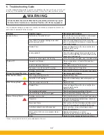
refer to the troubleshooting section of this manual to help determine
the cause and associated solution.
4.3 Touchscreen Operation
4.3.1 Start-up and Home Screen
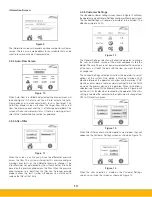
The display will turn on automatically when the system is powered
up. The first screen will display as shown below, see Figure 5. This
screen will also act as a screen saver when the blower is not oper-
ating. After 2-3 minutes of non-use the display will change to this
screen. When you want to use the unit, just tap the screen with
your finger and it will change to the main display screen shown in
Figure 6.
Figure 5
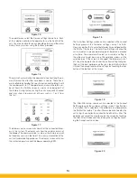
The home display screen shown in Figure 6 will be displayed during
operation. This will act as your status screen and be your gateway
to other screens. The screens are broken up in groups:
Basic
– These are your status screens for filters and blower.
Customer settings
– These screens are for the customer to make
setting changes to the unit.
Optional screens
– These screens are based on customer selected
options like Auto-Flow, After Filter monitoring or unique screens
required for a special application. These screens are based on cus-
tomer order and loaded at the factory.
Summary of Contents for SmogHog SHM-C
Page 1: ...SMOG HOG Media Mist Collector Owner s Manual Models SHM C SHM F...
Page 6: ...Page intentionally left blank...
Page 8: ...4 FIGURE 1B SHM Equipment Description 61 10113 FIGURE 1A SHM Equipment Description...
Page 13: ...9 61 10126 FIGURE 4 Remote Panel Touchscreen Connection...
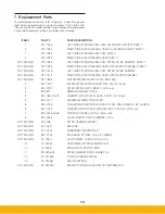
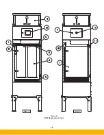
Page 23: ...19 Figure 6 SHM Replacement Parts SHM 11C SHM 11F...
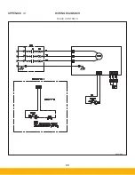
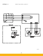
Page 24: ...20 APPENDIX A1 WIRING DIAGRAMS BASIC CONTROLS 04 001682...
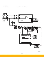
Page 25: ...21 REMOTE PANEL BASIC CONTROLS 04 001799 APPENDIX A2...
Page 26: ...22 ONE BLOWER AND CONTROLS 04 001695 APPENDIX A3...
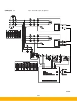
Page 27: ...23 TWO BLOWER AND CONTROLS 04 001696 APPENDIX A4...
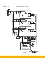
Page 28: ...24 THREE BLOWER AND CONTROLS 04 001697 APPENDIX A5...
Page 29: ...25 REMOTE PANEL TOUCH CONTROLS 04 001802 APPENDIX A6...
Page 30: ...26 ONE BLOWER AND REMOTE CONTROLS 04 001798 APPENDIX A7...
Page 31: ...27 TWO BLOWER AND REMOTE CONTROLS 04 001797 APPENDIX A8...
Page 32: ...28 THREE BLOWER AND REMOTE CONTROLS 04 001796 APPENDIX A9...
Page 33: ...29 575 480 TRANSFORMER 04 001717 APPENDIX A10...
Page 36: ...32...
Page 37: ...33...


