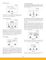
Figure 15
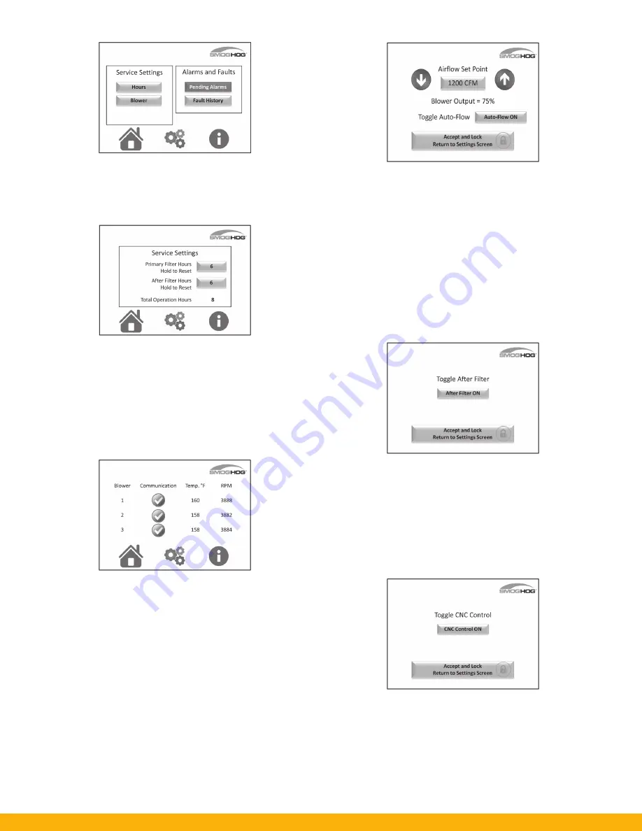
The operator can select the Service settings shown here. Each
of the selection will allow the operator to see the health of the
unit. You are also able to see any pending alarms and the alarm
history for your system using the buttons provided.
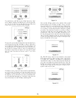
Figure 16
The service hours will allow the operator to see how long the pri-
mary filter and the after filter have been in service. These hours
are resettable by holding the specific button and holding it until
the number resets to 0. The operator can also see the total num-
ber of hours the SHM has been in service since being built at
the factory. During factory testing the units are quality checked
and may show a low amount of hours such as 1 or 2 from
this test.
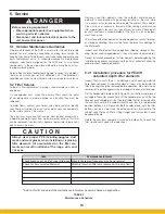
Figure 17
The blower service screen will show all of the connected blow-
ers in the system. The display will show the communication of
the blower. The communication is setup at the factory and will
not need any service in the field. This is only an indication of the
unit for troubleshooting purposes. The display screen will show
the motor temperature and the blower operating RPM.
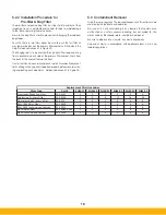
The Auto-Flow Settings screen can be selected in the Locked
Settings group on the Customer settings screen. The Auto-
Flow is an option that is selected at order time and loaded into
the SHM at the factory. The Auto-Flow Settings will allow the
unit to maintain a precise operating point based on a desired
air volume. The operator will select an air volume setting in
the airflow set point box using the up/down arrows or the
selection box. If the screen is changed, the blower will shut
off. Once the operator has found the air flow setting that gives
their unit the best performance they can touch the Auto-Flow
ON and then accept and lock the settings by touching the lock
button at the bottom of the screen.
Figure 19
The After-Filter setup screen can be selected in the Locked
Settings group on the customer settings screen. The after-filter
is an option that is selected at the order time and loaded into
the SHM at the factory. The after-filter can be monitored by the
unit using its controller to monitor the health of this filter. The
operator can select the monitoring on this screen by touching
the After-Filter ON box and then locking the settings by touch-
ing the Accept and Lock box.
Figure 20
Figure 18
14
Summary of Contents for SmogHog SHM-C
Page 1: ...SMOG HOG Media Mist Collector Owner s Manual Models SHM C SHM F...
Page 6: ...Page intentionally left blank...
Page 8: ...4 FIGURE 1B SHM Equipment Description 61 10113 FIGURE 1A SHM Equipment Description...
Page 13: ...9 61 10126 FIGURE 4 Remote Panel Touchscreen Connection...
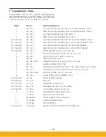
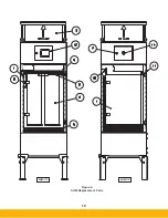
Page 23: ...19 Figure 6 SHM Replacement Parts SHM 11C SHM 11F...
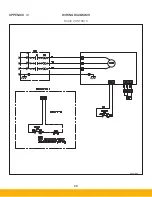
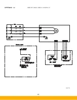
Page 24: ...20 APPENDIX A1 WIRING DIAGRAMS BASIC CONTROLS 04 001682...
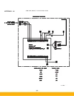
Page 25: ...21 REMOTE PANEL BASIC CONTROLS 04 001799 APPENDIX A2...
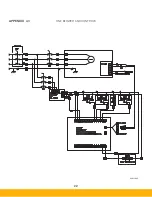
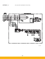
Page 26: ...22 ONE BLOWER AND CONTROLS 04 001695 APPENDIX A3...
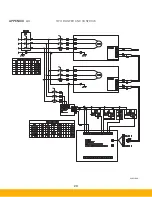
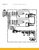
Page 27: ...23 TWO BLOWER AND CONTROLS 04 001696 APPENDIX A4...
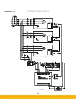
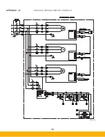
Page 28: ...24 THREE BLOWER AND CONTROLS 04 001697 APPENDIX A5...
Page 29: ...25 REMOTE PANEL TOUCH CONTROLS 04 001802 APPENDIX A6...
Page 30: ...26 ONE BLOWER AND REMOTE CONTROLS 04 001798 APPENDIX A7...
Page 31: ...27 TWO BLOWER AND REMOTE CONTROLS 04 001797 APPENDIX A8...
Page 32: ...28 THREE BLOWER AND REMOTE CONTROLS 04 001796 APPENDIX A9...
Page 33: ...29 575 480 TRANSFORMER 04 001717 APPENDIX A10...
Page 36: ...32...
Page 37: ...33...


