


5.1 General Maintenance Guidelines
Proper maintenance of the SHM is essential for the unit to provide
excellent oil mist collection capabilities and long-term service. By
keeping the unit well-maintained, you will also reduce operating and
parts replacement costs. A scheduled preventive maintenance
program, specifically designed for the SHM and its associated
components, is the best possible method to ensure the unit stays
in proper working order.
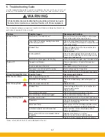
Refer to Section 6 for troubleshooting guide to correct any problems
that may occur with your oil mist collection unit. If the problem or
condition continues, contact Parker customer service for assistance.
5.2 Filter Service
Automatic filter replacement warnings should display on units so
equipped.
On unequipped units, when the primary filters reach the point
of not being able to maintain proper unit function they must be
replaced.
To order filters, contact your Parker sales representative. Identify
your filter part number from your sales order, your unit nameplate,
or the inside cover of this manual.
The aluminum mesh pre-filter can be washed and rinsed with a
moderately powerful spray from a power-washer or hose. This filter
can be replaced if contaminants become impossible to remove or
due to excessive wear.
Always wear proper PPE including goggles, dust
mask and work gloves when installing or replacing
filter elements. Oil accumulated on the filter ele-
ments can result in irritation of the lungs, skin, and
/ or eyes.
5.2.1 Installation procedure for PEACH
saturated depth filter elements
Inspect filters to verify there is no damage and all packing materials
have been removed. A supportive piece of foam may be inside the
filter tube and should be removed before operation. Be careful upon
removal not to pull too aggressively to dislodge the inner-most end cap.
Set the header plate (balloon #3 in Figure 5A) on the floor and place a
cartridge in the center of each hole. Lift the header plate up until the top
flange of each cartridge rests on the plate. Slide the filter assembly onto
the cam-bar and into the cabinet while the cam-bar is in the lowered
position (balloon #4 in Figure 5A) (both handles down) until the filter
bottoms out on a stop. Once the entire cassette is inserted into the
cabinet verify that each filter is sitting straight and fully seated in each
header plate hole.
Rotate the cam-bars upward as illustrated in balloon #5 to push the
filter up and seal it against the tube sheet.
!
D A N G E R
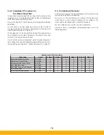
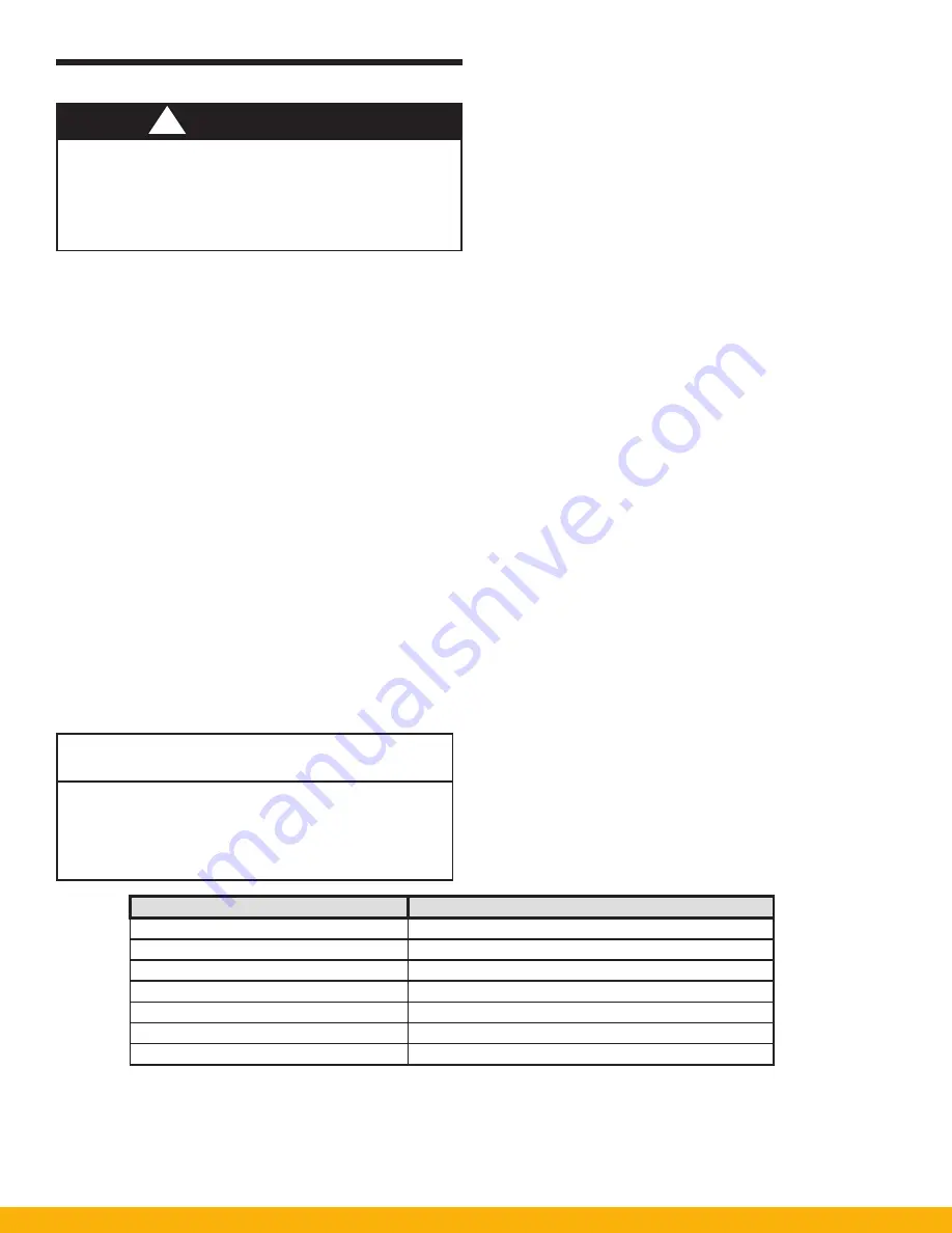
Task
Maintenance Interval
Check Sump Level, Verify Proper Drainage Weekly (increased frequency may be necessary)
Check For Accumulated Material
Monthly (or when filters are replaced or bin emped)
*Add to this list and adjust the maintenance interval as necessary based on applicaon.
TABLE 4
Maintenance Schedule
Remove used filter elements from the collector and dispose of
properly, in accordance with governing restrictions. Be sure there
is no excess oil or residue build-up inside the primary filter cabinet.
Clean or rinse as necessary. Inspect all filter sealing cam bars and
filter support parts for unusual signs of wear or failure. Checking all
gaskets and seals is recommended at this time, as well as replace-
ment if necessary.
The surface of the filter element can be damaged as a result of improp-
er moving or handling. Care must be taken to prevent any damage to
the filter media.
Inspect each filter element for damage from shipping, storage or han-
dling. Do not use damaged elements, they may leak or fail prematurely.
Review installation procedures for filter elements before beginning the
installation procedures and accessing the oil mist collector. Follow the
proper lockout, tagout procedures.
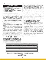
5. Service
Before servicing equipment:
• Wear appropriate protective equipment when
servicing oil mist collector.
• Disconnect and lockout electrical power to the
unit and control panel.
C A U T I O N
15
Summary of Contents for SmogHog SHM-C
Page 1: ...SMOG HOG Media Mist Collector Owner s Manual Models SHM C SHM F...
Page 6: ...Page intentionally left blank...
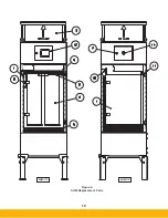
Page 8: ...4 FIGURE 1B SHM Equipment Description 61 10113 FIGURE 1A SHM Equipment Description...
Page 13: ...9 61 10126 FIGURE 4 Remote Panel Touchscreen Connection...
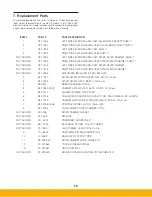
Page 23: ...19 Figure 6 SHM Replacement Parts SHM 11C SHM 11F...
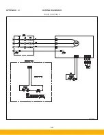
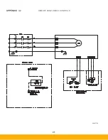
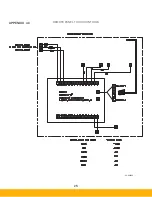
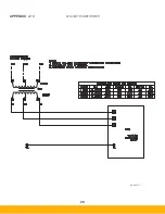
Page 24: ...20 APPENDIX A1 WIRING DIAGRAMS BASIC CONTROLS 04 001682...
Page 25: ...21 REMOTE PANEL BASIC CONTROLS 04 001799 APPENDIX A2...
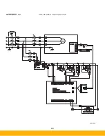
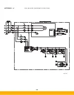
Page 26: ...22 ONE BLOWER AND CONTROLS 04 001695 APPENDIX A3...
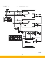
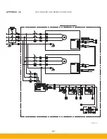
Page 27: ...23 TWO BLOWER AND CONTROLS 04 001696 APPENDIX A4...
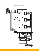
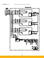
Page 28: ...24 THREE BLOWER AND CONTROLS 04 001697 APPENDIX A5...
Page 29: ...25 REMOTE PANEL TOUCH CONTROLS 04 001802 APPENDIX A6...
Page 30: ...26 ONE BLOWER AND REMOTE CONTROLS 04 001798 APPENDIX A7...
Page 31: ...27 TWO BLOWER AND REMOTE CONTROLS 04 001797 APPENDIX A8...
Page 32: ...28 THREE BLOWER AND REMOTE CONTROLS 04 001796 APPENDIX A9...
Page 33: ...29 575 480 TRANSFORMER 04 001717 APPENDIX A10...
Page 36: ...32...
Page 37: ...33...


