


iii
SAFETY PRECAUTIONS
We have provided many important safety messages in this manual. Always read and obey all safety messages.
• Use proper lifting and rigging equipment to install your
dust collector.
• The dust collector should be properly grounded.
• Disconnect power before servicing.
• Replace all access panels before operating.
• Electrical connections should only be made by qualified per-
sonnel, and be in accordance with local and national codes
and regulations.
• Do not use in explosive atmospheres unless the dust
collector is equipped with the appropriate accessories.
• Keep flammable materials and vapors, such as gasoline,
away from dust collector.
• The unit should be inspected frequently and dirt removed to
prevent excessive accumulation which may result in flash-
over or fire damage.
• Operate only in a safe and serviceable condition.
• Do not allow any individual to put lit cigarettes or any
burning objects into the hood or ducting of any dust
control system.
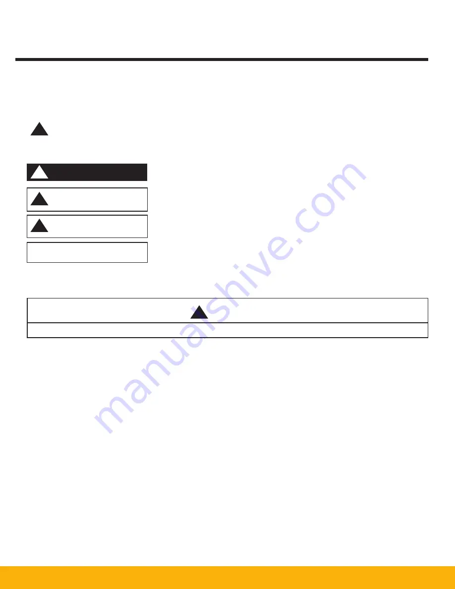
!
!
D A N G E R
This is the safety alert symbol.
This symbol alerts you to potential hazards that can kill or hurt you and others. All safety messages will follow the
safety alert symbol and the word “DANGER”, “WARNING” or “CAUTION”. These words mean:
Indicates a hazardous situation which, if not avoided, will result in death or serious
injury.
Indicates a potentially hazardous situation which, if not avoided, could result in death
or serious injury.
Indicates a potentially hazardous situation which, if not avoided, may result in minor
or moderate injury.
CAUTION used without the safety alert symbol indicates a potentially hazardous
situation which, if not avoided, may result in property damage.
IMPORTANT SAFETY INSTRUCTIONS
To reduce the risk of fire, electric shock, or injury when using the air cleaner, follow these basic precautions:
!
WARNING
!
WARNING
!
C A U T I O N
C A U T I O N
Summary of Contents for SmogHog SHM-C
Page 1: ...SMOG HOG Media Mist Collector Owner s Manual Models SHM C SHM F...
Page 6: ...Page intentionally left blank...
Page 8: ...4 FIGURE 1B SHM Equipment Description 61 10113 FIGURE 1A SHM Equipment Description...
Page 13: ...9 61 10126 FIGURE 4 Remote Panel Touchscreen Connection...
Page 23: ...19 Figure 6 SHM Replacement Parts SHM 11C SHM 11F...
Page 24: ...20 APPENDIX A1 WIRING DIAGRAMS BASIC CONTROLS 04 001682...
Page 25: ...21 REMOTE PANEL BASIC CONTROLS 04 001799 APPENDIX A2...
Page 26: ...22 ONE BLOWER AND CONTROLS 04 001695 APPENDIX A3...
Page 27: ...23 TWO BLOWER AND CONTROLS 04 001696 APPENDIX A4...
Page 28: ...24 THREE BLOWER AND CONTROLS 04 001697 APPENDIX A5...
Page 29: ...25 REMOTE PANEL TOUCH CONTROLS 04 001802 APPENDIX A6...
Page 30: ...26 ONE BLOWER AND REMOTE CONTROLS 04 001798 APPENDIX A7...
Page 31: ...27 TWO BLOWER AND REMOTE CONTROLS 04 001797 APPENDIX A8...
Page 32: ...28 THREE BLOWER AND REMOTE CONTROLS 04 001796 APPENDIX A9...
Page 33: ...29 575 480 TRANSFORMER 04 001717 APPENDIX A10...
Page 36: ...32...
Page 37: ...33...


