3
1. Important Notice
This manual contains important safety information and precau-
tionary measures. It is impossible to list all potential hazards
associated with every collection system in each application.
Proper use of the equipment should be discussed with Parker.
Operating personnel should be aware of, and adhere to, the most
stringent safety procedures.
2. Introduction
Thank you for selecting Parker oil mist collection equipment
to assist you in your commitment to a clean and safe envi-
ronment. We trust that in purchasing our product, you have
recognized our commitment to offering air cleaning equipment
which is engineered to each oil mist collection need and manu-
factured to the highest standards. If at any time you have a ques-
tion about oil mist collection, please do not hesitate to call Parker
customer service.
The purpose of this manual is to provide the proper operating
and maintenance guidelines for the SHM system supplied
by Parker. As you review this manual, refer to Figure 1 for
assistance in identifying oil mist collector parts.
The SHM oil mist collector has been designed to provide you
with exceptional oil mist collection capabilities and reliable, long
term field operation. We suggest that you thoroughly review this
manual prior to installation and startup of your system.
If your SHM has optional equipment included as part of your
order, specific operations and maintenance manuals for these
accessory systems will be included. If applicable, site specific
installation and other drawings will also be included.
If you require assistance in the installation, startup, operation,
maintenance, or troubleshooting of your air cleaning equipment,
contact your local Parker sales representative.
2.1 SMOG-HOG Nomenclature
SMOG-HOG oil mist air cleaners are available in a variety of
configurations and sizes. The model string for each given unit
represents the base configuration. The model number completely
identifies the design and can be found on the unit nameplate.
SHM models are defined according to descriptions listed below
(see bold):
SHM-XXX
Filter type
Quantity of filter modules deep
Quantity of filter modules wide
C - PEACH Saturated Depth
F - Fiberglass Bag Filter
Models SHM-11C, SHM-12C, SHM-21C, SHM-31C,
SHM-22C, & SHM-32C
Models SHM-11F, SHM-12F, SHM-21F, SHM-31F,
SHM-22F, SHM-32F
The SMOG-HOG is a free standing, self contained, multistage,
oil mist filtering unit with inlet sump or direct mount flange,
mechanical prefilter, primary filter, blower cabinet, and controls.
Optional after filters are available for third stage filtration.
2.2 Equipment Description
This section will briefly describe each component in the SHM
and its role in the system’s operation.
Inlet Sump
Most units will include an inlet sump with multiple 10˝ inlets
where all incoming dirty air will enter. The sump provides an
expanded volume allowing contaminant to drop out of the airst-
eam reducing loading on the filters. A 1-1/2” FNPT coupling is
included at the peak of a sloped bottom allowing the collected
contaminant to be reclaimed or drained.
Filter Cabinet
Each unit has a filter access door that provides access to both
the prefilter and primary filter for service and replacement. The
mesh prefilter rests on tracks near the bottom of the cabinet.
The PEACH coalescing filter option is mounted on a removable
cassette secured by a cam bar mechanism. The fiberglass bag
option uses a hanging rod system.
Filter Elements
Stage 1: Mist-Stop fine fiber aluminum mesh
Stage 2: Primary coalescer featuring PEACH Saturated Depth
Coalescing Technology - or - fiberglass bag
Blower Cabinet
Most units will have a blower cabinet where the motorized
impeller style blower is housed, as well as the electrical controls.
2.3 Principal Operation
The purpose of the SHM is to collect fugitive mist generated
by various industrial processes during operation. The collected
contaminate is drained off of the coalescing filters into the sump
below or directly back into the machine. The sump is attached
to a drain system of the customers choice for recycling or dis-
posal, or emptied manually at regular intervals.
Do not let the oil level in the sump reach the height
of the air inlet opening.
Differential Pressure
Differential pressure, also referred to as pressure drop (Δ P), is
an indication of the resistance to airflow across the filter ele-
ments. Differential pressure is commonly measured in inches of
water column (W.C.) or Pascals (Pa). It is normal for the differ-
ential pressure to increase as the collector operates. Any sud-
den increase or decrease in differential pressure may indicate
a problem in the collector (blinded filters, leaks or other cause)
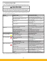
that requires immediate attention. See trouble shooting guide in
Section 6 for assistance.
The operating differential pressure displayed on the unit
will typically run between 0.5 to 4 in. W.C. (124 to 995 Pa) for
a Fiberglass Bag filter, and between 0.75 to 4 in. W.C. (187 to
995 Pa) for a Coalescing Cartridge filter. The expected pressure
range for the after-filters is 0.5 to 3.0 in. W.C. (124 to 746 Pa).
C A U T I O N
Summary of Contents for SmogHog SHM-C
Page 1: ...SMOG HOG Media Mist Collector Owner s Manual Models SHM C SHM F...
Page 6: ...Page intentionally left blank...
Page 8: ...4 FIGURE 1B SHM Equipment Description 61 10113 FIGURE 1A SHM Equipment Description...
Page 13: ...9 61 10126 FIGURE 4 Remote Panel Touchscreen Connection...
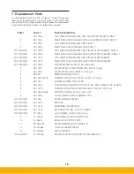
Page 23: ...19 Figure 6 SHM Replacement Parts SHM 11C SHM 11F...
Page 24: ...20 APPENDIX A1 WIRING DIAGRAMS BASIC CONTROLS 04 001682...
Page 25: ...21 REMOTE PANEL BASIC CONTROLS 04 001799 APPENDIX A2...
Page 26: ...22 ONE BLOWER AND CONTROLS 04 001695 APPENDIX A3...
Page 27: ...23 TWO BLOWER AND CONTROLS 04 001696 APPENDIX A4...
Page 28: ...24 THREE BLOWER AND CONTROLS 04 001697 APPENDIX A5...
Page 29: ...25 REMOTE PANEL TOUCH CONTROLS 04 001802 APPENDIX A6...
Page 30: ...26 ONE BLOWER AND REMOTE CONTROLS 04 001798 APPENDIX A7...
Page 31: ...27 TWO BLOWER AND REMOTE CONTROLS 04 001797 APPENDIX A8...
Page 32: ...28 THREE BLOWER AND REMOTE CONTROLS 04 001796 APPENDIX A9...
Page 33: ...29 575 480 TRANSFORMER 04 001717 APPENDIX A10...
Page 36: ...32...
Page 37: ...33...


