5
Ensure there is adequate access to the electrical components with
ducting installed.
3.3 Discharge Component Installation
Ensure to position the unit so that the clean air discharge is directed
into an open area free of obstructions and with consideration for
personnel safety.
3.4 Mechanical Installation
CRUSH HAZARD
Use adequate safety measures when lifting and
assembling any heavy components. Consult your
plant safety personnel for recommendations.
Connect lifting slings and spreader bars to lifting lugs
with clevis pins. Use spreader bars to distribute the
load evenly. Location must be clear of all obstruc-
tions, such as utility lines or roof overhangs.
When the SHM unit is to be
mounted directly to a machine,
you
will be furnished with a mounting flange and drawing to illustrate
the bolt pattern and hardware required for proper mounting to their
equipment. Be sure to seal around the entire perimeter between the
mounting flange and the existing machine with an appropriate seal-
ant in a figure-eight pattern around each bolt hole.
Units with
sumps
utilize 10˝ inlets and optional collar flange(s) that
come mounted to the unit. They can be rearranged and mounted
however desired based on application needs. Be sure to use a poly-
urethane sealant or gasket to prevent leaks. It is recommended to use
ducting that is liquid tight to prevent leaks.
All other transitions, ducting or plenums required for unit set-up and
operation are not included with the equipment.
Unit should always be secured to the floor when
installed in this configuration.
Secure the unit at all four corners using the standard unit feet or exten-
sion leg foot pads. At least one of the two holes per foot pad on the
extension legs should be secured. See Figure 1 for reference.
Ceiling mounted
units are suspended by means of 1⁄2˝ threaded rods
(item #1 in Figure 3) which run through weld nuts (item #2 in Figure 3)
in the top corners of the units. Refer to Figure 2 for weld nut locations
on SHM-11 models. Additional support should be used for auxiliary
equipment or ducting. Do not suspend units larger than the SHM-11
from the ceiling.
The SMOG-HOG should not be used for support of
personnel or material. Check with local building code/
structural engineer to ensure proper installation to roof
truss or any other mounting method.
3. Installation
3.1 Inspection and Off Loading
As soon as your equipment arrives, it should be carefully inspected
to make certain that it is in good condition and that all items listed
on the packing list have been received. Even though the items are
carefully loaded and tied down at the time of shipment, it is possible
for them to be damaged or become dislodged in transit.
Report any damage(s) and/or shortage(s) immediately. It becomes
increasingly difficult for either the carrier or the supplier to assume
responsibility for any damages after too much time has elapsed.
Check all loads separately.
The following steps should be taken immediately upon receipt
of your shipment; this will assure and expedite claim payments
and replacement of missing or damaged items.
1. Begin your inspection of the shipment BEFORE it is unloaded.
2. Check for damage to any exposed items, particularly at the tie-
down locations.
3. Photograph any damage. Do this BEFORE the equipment is
unloaded.
4. Check Bill of Lading quantities and description. Note any discrep-
ancies on all copies of the Bill of Lading and have them acknowl-
edged (the carrier should sign). Damage description should also
be written directly on, or attached to, the Bill of Lading, and
should also be signed by the driver.
Contact the insurance company and the shipper at once so that
damages and/or shortages can be corrected and a claim can be
filed without delay.
TIP OVER HAZARD
Lift the SHM unit and components by the packing
skids or on the lifting eyes located on the top of the
unit in each corner. Do not lift the unit by placing
lift truck forks through the legs on the underside of
the unit.
3.2 Installation Preparation and Planning
Prior to the actual installation of the SHM, the location should
be readied. This would include having an adequate lay-
down area for all components, and access for the crane,
forklifts and other machinery. The unit will come pre-assembled.
The majority of installation will be electrical hook-up, and hanging,
mounting, or securing the unit. An electrical source, lighting and
other equipment should be readily available to aid in the installation.
In most cases engineering drawings of your specific equipment and
options will be provided. These and all available documentation
for your system should be thoroughly reviewed prior to beginning
any installation work. This includes the unit and electrical controls.
Ensure to leave an appropriate amount of room around your unit to
allow for maintenance and servicing. A minimum of 2-1/2 feet (0.76
m) of clearance is recommended for service in front of the filter
access door and 3 feet (1 m) for the rear electrical access per NEC.
!
D A N G E R
!
D A N G E R
C A U T I O N
C A U T I O N
Summary of Contents for SmogHog SHM-C
Page 1: ...SMOG HOG Media Mist Collector Owner s Manual Models SHM C SHM F...
Page 6: ...Page intentionally left blank...
Page 8: ...4 FIGURE 1B SHM Equipment Description 61 10113 FIGURE 1A SHM Equipment Description...
Page 13: ...9 61 10126 FIGURE 4 Remote Panel Touchscreen Connection...
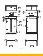
Page 23: ...19 Figure 6 SHM Replacement Parts SHM 11C SHM 11F...
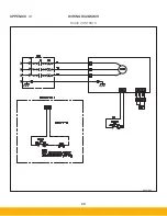
Page 24: ...20 APPENDIX A1 WIRING DIAGRAMS BASIC CONTROLS 04 001682...
Page 25: ...21 REMOTE PANEL BASIC CONTROLS 04 001799 APPENDIX A2...
Page 26: ...22 ONE BLOWER AND CONTROLS 04 001695 APPENDIX A3...
Page 27: ...23 TWO BLOWER AND CONTROLS 04 001696 APPENDIX A4...
Page 28: ...24 THREE BLOWER AND CONTROLS 04 001697 APPENDIX A5...
Page 29: ...25 REMOTE PANEL TOUCH CONTROLS 04 001802 APPENDIX A6...
Page 30: ...26 ONE BLOWER AND REMOTE CONTROLS 04 001798 APPENDIX A7...
Page 31: ...27 TWO BLOWER AND REMOTE CONTROLS 04 001797 APPENDIX A8...
Page 32: ...28 THREE BLOWER AND REMOTE CONTROLS 04 001796 APPENDIX A9...
Page 33: ...29 575 480 TRANSFORMER 04 001717 APPENDIX A10...
Page 36: ...32...
Page 37: ...33...


