Page 2
/ Bulletin 100-50-1
LEGEND
TEST POINTS and PIN JUMPERS
TP1
Test Point 1
positive connection point to millivolt voltmeter to
read set point temperature
TP2
Test Point 2
negative connection point as above
P1
Pin Jumper 1
voltage or current input selector
P2
Pin Jumper 2
TTL logic or 24-120 VAC Pulse Width Modulated
signal input selector
P4
Pin Jumper 4
internal power selector - DO NOT CHANGE
P5
Pin Jumper 5
force valve open switch - valve will open and will
remain open as long as jumper is installed
P6
Pin Jumper 6
force valve closes switch - valve will close and
remain closed while jumper is installed
P7
Pin Jumper 7
temperature sensor enable selector
P8
Pin Jumper 8
“open on rise” logic selector
P9
Pin Jumper 9
“close on rise” logic selector
P10
Pin Jumper 10
SEI .5 to SEI-11 valve selector (1596 step stroke)
P11
Pin Jumper 11
CDS-8 valve selector (3193 step stroke)
P12
Pin Jumper 12
all other valves selector (6386 step stroke)
WIRING CONNECTIONS
PID+
connect positive side of 4-20 ma or 0-10 VDC signal
INPUT
connect negative side of 4-20 ma or 0-10 VDC signal
BLACK
connect black valve lead
WHITE
connect white valve lead
GREEN
connect green valve lead
RED
connect red valve lead
Square Wave
connect TTL logic (5 VDC) step signal
DIRECTION
connect TTL logic direction signal. 5 VDC = OPEN, 0 VDC
= CLOSE
24 VAC
2 connections for 24 VAC or 24 VDC @ 40 VA isolated
power input
PUMPDOWN
2 connections for pumpdown contacts. When “shorted”
the valve will close and remain closed. When “open” the
valve will control normally. For alternate operation see
5.
under “Wire the Board” pg 3.
TEMP SENSOR
2 connections for supplied 2 k type B thermistor. Not
polarized.
Blank
no connection - for high voltage input isolation.
AC PULSE
for one leg of 24-120 VAC, 3-30 second Pulse Width
Modulated signal.
Blank
no connection - for high voltage input isolation.
AC PULSE
for the other leg of 24-120 VAC, 3-30 second Pulse Width
Modulated signal.
NOTE:
Not all inputs or pin jumpers will be used. See Configuration
instructions.
Valves of any capacity except 2500 step
valves such as CDST-4 & CDST-7 (see note
on page 2). Pin jumpers on the face of the
board will permit changes in board control
parameters to suit particular applications.
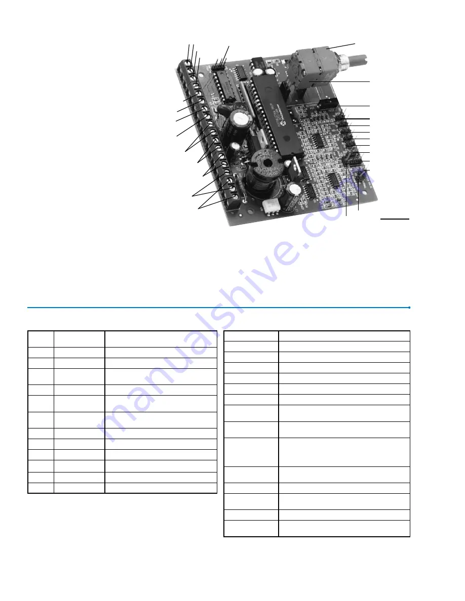
Figure 1 shows the layout of the board with
connection points labeled.
Figure
1
P6
P5
P1
P2
P12
P11
P10
P9
P8
TP2
Set Point
Potentiometer
TP1
P7
24-120 VAC
PWM Pulse
No Conn.
Temp. Sensor
Pumpdown
24VAC
TTL
Direct.
TTL
Wave
Red
Green
PID+
PID-
Black
White
P4
The Sporlan TCB has been developed to
allow the control of most Sporlan electric
valves with the use of a generic PID or
similar controller, or with the addition of the
Sporlan sensor, to perform as a stand alone
temperature controller. In addition to the 0
to 10 volt DC or 4 to 20 milliamps signal
usual from PID controllers, the TCB can be
configured to modulate a valve in response
to a TTL (5 volt) signal, or a 24-120 volt
AC pulse of three to thirty seconds duration.
The
TCB
may be ordered less potentiometer
if an external signal (e.g. 4-20ma) is to be
used. See ordering instructions. The board
was designed for easy standoff mounting
in electrical panels supplied by others, and
with screw terminal wiring connections.
The unit is small (3.5” x 4.0”) and eco-
nomical and requires only 24 volts AC or
24 VDC at 40 VA for both board and valve
power. Operating ambient and storage tem-
perature is -10°F to 160°F.
The
TCB
has been designed to work with
Sporlan SEI/SEH Electric Expansion
Valves, CDS Electric Suction Control
Valves, and SDR Electric Hot Gas Bypass
FOR USE ON REFRIGERATION and/or AIR CONDITIONING SYSTEMS ONLY
Bulletin 100-50-1, December 2010 supersedes Bulletin 100-50-1, January 2006 and all prior publications.


