background image

5

HOOD ADJUSTMENT

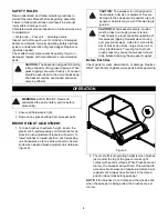
1. The hood can be adjusted to change the deflection 

of the material being handled by loosening the wing 
nuts on both sides of the hood and sliding the hood 
up or down (figure 3).

2. If sweeping at a high rate of speed, the hood should 

be raised to deflect the material to the back of the 
basket.

3. If sweeping at a low rate of speed, the hood should 

be lowered until material goes to the back of the 
basket.

BRUSH CARE AND REPLACEMENT

Brush Removal

Never allow the brush bristles to remain in a bent position 
on any object for any length of time as they can take a 
set. Should the bristles take a set from use, reverse the 
brushes on the reel shaft as follows:

1. Turn the sweeper upside down on a workbench or 

the ground.

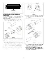
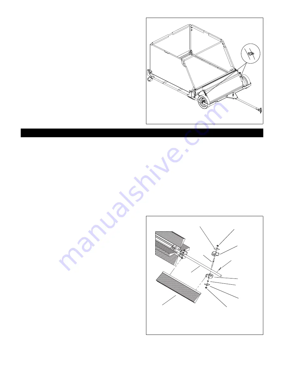
2. The brush stud has a collar fitting against one of the 

brush brackets holding it against the reel shaft 
(figure 4).

3. Remove the speed nuts and brush clamps from the 

end of the studs on the sides with the collar.

4. Remove the brushes from the brush bracket slots.

5. Remove the speed nuts and brush clamps from the 

opposite end of the studs. DO NOT remove the 
speed nut or the stud will fall out of reel shaft 
releasing the brush brackets.

Brush Installation

1. Turn the reel shaft to position the brush strips in the 

slots of the brush brackets held on the stud by the 
speed nut (figure 4).

2. Position the brush clamps and finger tighten nuts. 

Be sure brushes are all the way down in all the 
brush brackets.

3. Brushes will be staggered with a slight overlap 

(figure 5). Tighten lock nuts to ensure brushes are 
held firmly in place.

4. Turn the reel shaft so the installed brush strips are 

on the bottom.

5. Repeat steps 1 – 4 for the remaining brushes.

6. Tighten all nuts. Torque to 4.2 – 4.6 lb.ft (61 – 67 

N-m).

LUBRICATION

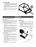
1. Occasional lubrication of the sweeper will lengthen 

the service life.

2. Check grease in wheels before operating unit. Each 

wheel has a grease fitting in the hub near the axle. 
Add grease until grease is forced out through gap of 
hub at axle.

3. Place a few drops of oil in the swivel bearings and 

axle of the casters every time the machine is used.

 Figure 3

MAINTENANCE

 Figure 4

Brush

Clamp

Reel Shaft

Brush 

Bracket

1/4 Speed 

Nut

Clamp

Stud

Collar

Serrated 

Flange Nut

Brush 

Bracket

Roll Pin

Serrated 

Flange Nut

Summary of Contents for Suburbanite 895803

Page 1: ...Owner Operator Parts Manual Model 895803 Mesh Bottom 895802 Hard Bottom 04155800D 1 12 Printed in USA Suburbanite 36 Trailing Lawn Sweeper ...

Page 2: ...r disclaims liability for any claims or damages whether warranty property damage personal injury or death arising out of the use of unauthorized replacement parts DISCLAIMER Parker reserves the right to discontinue make changes to and add improvements upon its products at any time without public notice or obligation The descriptions and specifications contained in this manual were in effect at pri...

Page 3: ...haser of this unit was instructed by the seller on safe and proper operation If unit is to be used by someone other than original purchaser loaned rented or sold ALWAYS provide this manual and any needed safety training before operation 1 DANGER SAFETY DANGER IMMINENTLY HAZARDOUS SITUATION If not avoided WILL RESULT in death or serious injury WARNING POTENTIALLY HAZARDOUS SITUATION If not avoided ...

Page 4: ...ent operating height is when brushes just contact the top of the grass or make light contact with paved surfaces When brushes are set too low the sweeper will pull hard This will lead to excessive brush wear and require premature brush replacement Always have brushes in the raised position when transporting sweeper NOTE If the brushes do not rotate and the wheels slide when the sweeper is being pu...

Page 5: ...d brush clamps from the opposite end of the studs DO NOT remove the speed nut or the stud will fall out of reel shaft releasing the brush brackets Brush Installation 1 Turn the reel shaft to position the brush strips in the slots of the brush brackets held on the stud by the speed nut figure 4 2 Position the brush clamps and finger tighten nuts Be sure brushes are all the way down in all the brush...

Page 6: ...cavity figure 7 It may be necessary to apply force to the plastic tubes Tubes are resilient and should fit tightly NOTE The left and right side are determined from the Operator s position 3 Assemble pinion part no P74 79 BL to the left side of shaft and pinion part no P74 78 BR to the right side figure 7 4 Push the pinion onto the shaft which will force the dowel out of the pinion leaving the roll...

Page 7: ... 32 81 cm H x 46 117 cm W Bottom Mesh Hard Material Reinforced Vinyl Capacity cu ft 17 Brushes Eight Polypropylene Steel Backed Brushes in Four Staggered Rows Height Adjustment Variable Height Adjustment for Brushes Independent of the Frame Ball Bearings Sealed Ball Bearings on the Brush Axle for Extended Life Frame Tubular Steel Gears Sintered Pinion Wheels 10 5 x 2 5 Casters Heavy Duty Rear Cast...

Page 8: ...8 SWEEPER UNIT ASSEMBLY PARTS LIST 1 2 3 4 5 6 7 35 8 9 10 11 12 32 31 32 13 11 31 16 28 14 15 17 23 22 33 20 21 22 23 18 24 19 34 36 27 34 27 30 17 26 37 42 41 40 39 3 3 4 4 5 25 29 ...

Page 9: ...od Front 20 P74 13 C 8 Bracket 21 P74 16 PLT 4 Plated Stud Zinc 22 P69 04 A 8 Clamp Brush Strip 23 06530100 8 Nut Flange Lock 25 20 YWZC 24 P1200 17 B 8 Brush Sweeper 25 P76 338 RF 1 Side Plate Right Hand 26 P74 78 RB 1 Pinion Right 27 P49 11 A 2 Clamp Hood 28 05946900 2 Bolt Hex 31 18 x 1 00 Grade 5 YWZC 29 06006125 6 Set Screw Square Head 30 P67 521 A 2 Roll Pin 3 16 x 1 3 4 31 06544000 4 Nut Ja...

Page 10: ...10 FRAME ASSEMBLY 1 13 23 31 3 30 19 26 25 19 32 25 19 27 2 16 30 12 12 10 35 11 25 19 30 18 29 18 19 30 28 24 4 30 23 21 20 18 17 22 30 15 13 23 8 9 18 29 6 33 34 7 14 5 35 13 19 12 11 19 36 ...

Page 11: ...r Flat Steel 344 x 688 x 065 YWZC 19 06437300 20 Washer Flat Steel 281 x 62 x 065 YWZC 20 P55 160 A 1 Spacer 500 OD x 625 L 21 P79 94 A 1 Knob Fluted 22 06435900 1 Washer Flat Steel 438 x 1 00 x 083 YWZC 23 05961600 6 Bolt Hex 25 20 x 2 50 Grade 5 YWZC 24 05947000 1 Bolt Hex 31 18 x 75 Grade 5 YWZC 25 05967100 8 Bolt Hex 25 20 x 2 00 Grade 5 YWZC 26 05952600 2 Bolt Hex 31 18 x 2 50 Grade 5 YWZC 27...

Page 12: ...ontour Head 10 05952500 4 Bolt Hex 1 4 20 x 1 5 Grade 5 11 05946900 4 Bolt Hex 5 16 18 x 1 00 Grade 5 12 06308400 8 Washer Lock 25 x 062 YWZC 13 06308600 4 Washer Lock 31 x 078 YWZC 14 06533200 8 Nut Hex 1 4 20 15 P92 28 20 Rivet Bulb Tite 16 06500012 4 Nut Nylock Flange 25 20 17 04295900 1 Wind Apron Not Shown 18 P360900 1 Basket Bottom Mesh Not Shown P89 57 C 1 Basket Bottom Hard Not Shown NOTE ...

Page 13: ... 1 Tongue Weldment 2 M88183 2 Ring Locking 3 04197800 2 Pin Hitch 4 P75 134 B 1 Yoke 5 P75 40 B 1 Hitch Plate Weldment 6 05946900 2 Bolt Hex 31 18 x 1 00 Gr 5 YWZC 7 06530200 2 Nut Nylok 312 18 YWZC 8 06700002 2 Pin Cotter 09 x 1 50 YWZC 1 2 2 3 3 4 7 8 8 6 5 ...

Page 14: ...e warranty service performed by an authorized Ariens Gravely Parker or Countax service representative To Find an Authorized Service Representative Warranty Code Product Group Warranty Period Consumer Use Warranty Period Commercial Use PA Log Splitters Brushes String Trimmers Edgers 3 Years 90 Days PB Professional Powered Brushes 3 Years 1 Year PC Tillers 2 Years 90 Days PD Vacuums Blowers Sweepers...

Page 15: ...vely parts or accessories Modifying the utility vehicle without express written authorization from the Ariens Company Operating the utility vehicle when it has not been completely and properly assembled and pre delivered by an authorized Gravely dealer Disclaimer Ariens Company may from time to time change the design of its products Nothing contained in this warranty shall be construed as obligati...

Page 16: ...Parker 655 West Ryan Street Brillion WI 54110 920 756 4688 Fax 920 756 2407 www ariens com www parkersweeper com ...

Reviews: