HY13-1526-001-M1/US
Torqmotor™ Service Procedure
TC, TS, TB, TE and TJ Series
Parker Hannifin Corporation
Hydraulic Pump/Motor Division
Greeneville, TN 37745 US
40
Install the
assembled
rotor set
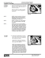
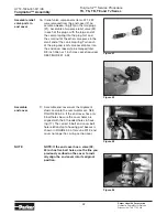
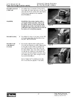
11. Install the assembled rotor set (7) onto wear
plate (8) with rotor counterbore and seal ring
side down and the splines into mesh with
the drive link splines.
Apply clean grease to a
new
seal ring (3)
and assemble it in the seal ring groove in
the rotor set.
NOTE
NOTE: It may be necessary to turn one
alignment stud out of the housing (17)
temporarily to assemble rotor set (7) or
manifold (6) over the drive link.
NOTE
NOTE: If necessary, go to the appropri-
ate, “Rotor Set Component Assembly
Procedure.”
NOTE
NOTE: The rotor set rotor counterbore
side must be down against wear plate for
drive link clearance and to maintain the
original rotor-drive link spline contact. A
rotor set without a counterbore and that
was not etched before disassembly can
be reinstalled using the drive link spline
pattern on the rotor splines if apparent,
to determine which side was down.
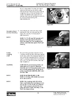
Figure 46
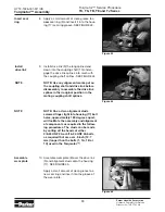
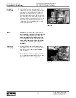
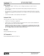
Figure 47
Torqmotor™ Assembly
NOTE: The manifold (6) is made up of
several plates bonded together perma-
nently to form an integral component.
The manifold surface that must contact
the rotor set has it’s series of irregular
shaped cavities on the largest circumfer-
ence or circle around the inside diameter.
The polished impression left on the mani-
fold by the rotor set is another indication
of which surface must contact the rotor
set.
Assemble
manifold
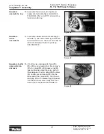
12. Assemble the manifold (6) over the align-
ment studs and drive link (9) and onto the
rotor set. Be sure the correct manifold sur-
face is against the rotor set.
Apply grease to a
new
seal ring (3) and
insert it in the seal ring groove exposed on
the manifold. SEE FIGURE 47.


