HY13-1526-001-M1/US
Torqmotor™ Service Procedure
TC, TS, TB, TE and TJ Series
Parker Hannifin Corporation
Hydraulic Pump/Motor Division
Greeneville, TN 37745 US
43
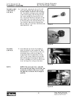
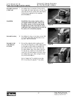
Figure 55
Assemble
cover bolts
18. Assemble the 5 or 6 special bolts (1, 1A,
1B or 1C) and screw in finger tight. Remove
and replace the two alignment studs with
bolts after the other bolts are in place. Al-
ternately and progressively tighten the bolts
to pull the end cover and other components
into place with a final torque of 25-30 ft. lbs.
(34-41 N m) for the five TC, TS, TB or six
TE Series 5/16 24 threaded bolts or six TJ
bolts. SEE FIGURE 55.
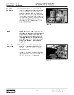
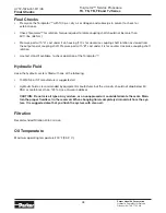
Figure 56
Torqmotor™ Assembly
NOTE
NOTE: The special bolts required for use
with the relief or shuttle valve (22, 24) end
cover assembly (2) are longer than the
bolts required with standard and cover
assembly. Refer to the individual service
parts lists or parts list charts for correct
service part number if replacement is
required.
Torque the
valve plugs
19. Torque the two shuttle valve plug assem-
blies (23) in end cover assembly to 9-12 ft.
lbs. (12-16 N m) if cover is so equipped.
SEE FIGURE 56.
Torque the two relief valve plug assemblies
(21) in end cover assembly to 45-55 ft. lbs.
(61-75 N m) if cover is so equipped.

