HY13-1527-M1/US
Torqmotor™ Service Procedure
TF, TG, TH and TL Series
Parker Hannifin Corporation
Hydraulic Pump/Motor Division
Greeneville, TN 37745 US
20
Disassembly and Inspection
Place
Torqmotor
in a vise
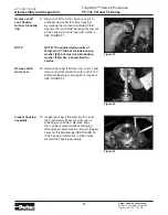
1. Place the Torqmotor™ in a soft jawed vise,
with coupling shaft (12) pointed down and
the vise jaws clamping firmly on the sides
of the housing (18) mounting flange or port
bosses. Remove manifold port O-Rings
(18A) if applicable.
WARNING
WARNING:
IF THE TORQMOTOR™ IS NOT
FIRMLY HELD IN THE VISE, IT COULD
BE DISLODGED DURING THE SERVICE
PROCEDURES, CAUSING INJURY.
Scribe alignment
mark & loose
valve plugs
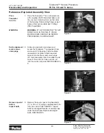
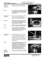
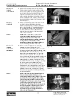
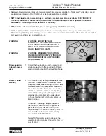
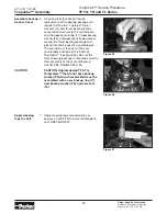
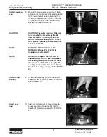
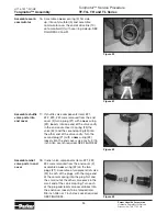
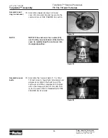
2. Scribe an alignment mark down and
across the Torqmotor™ components from
end cover (2) to housing (18) to facilitate
reassembly orientation where required.
Loosen two shuttle or relief valve plugs
(21) for disassembly later if included in end
cover. 3/16 or 3/8 inch Allen wrench or 1
inch hex socket required. SEE FIGURES 2 &
3.
Remove special
bolts &
inspect bolts
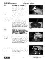
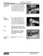
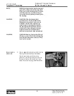
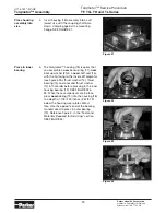
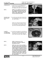
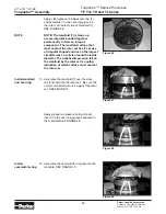
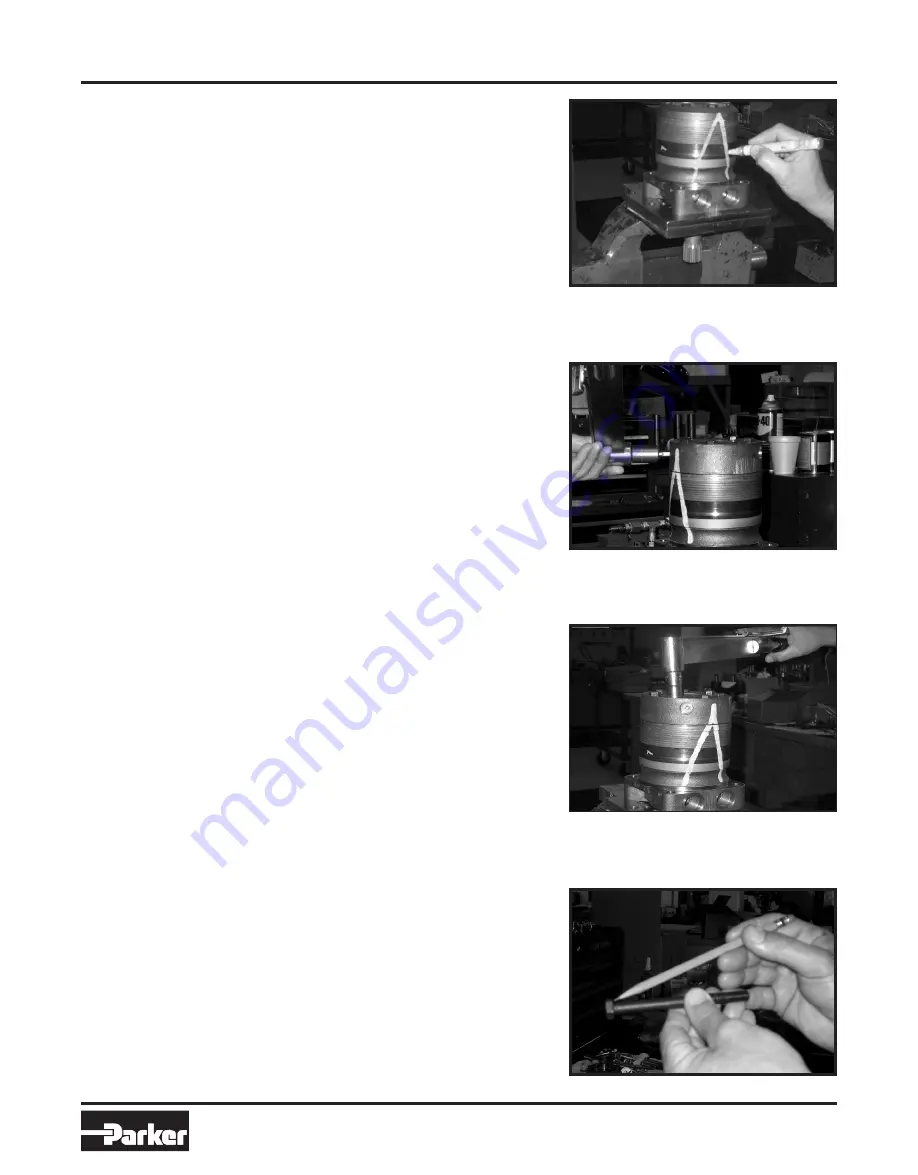
3. Remove the seven special ring head bolts
(1, 1A, 1B, or 1C) using an appropriate 9/16
inch size socket. SEE FIGURE 4. Inspect
bolts for damaged threads, or sealing rings,
under the bolt head. Replace damaged
bolts. SEE FIGURE 5.
Reference Exploded Assembly View
Figure 5
Figure 4
Figure 3
Figure 2


