Service/Spare Parts Manual
Series V16
MSG30-5526-M1/UK
17
Parker Hannifin
Pump & Motor Division Europe
Trollhättan, Sweden
Parker Hannifin
Pump & Motor Division Europe
Trollhättan, Sweden
Gauge ports EO and EP
Threshold current setting procedure
EO/EP with negative control characteristics (M code)
With a de-energized solenoid (EO/EP) the motor will be
kept at maximum displacement.
1. Make sure that the motor has been supplied with the
correct modulating spring (ordering code and name
plate information should agree). The hydraulic oil
should be 50°C.
2. Install a 0 – 600 bar gauge in port X1.
3. Turn the adjustment screw counterclockwise to en-
sure that the threshold spring is unloaded.
4. Apply desired threshold current (at this current the
control starts to go to min. displacement). Standard
factory setting is:
500mA (12V)
250mA (24V), valid for motors without displacement
limiter on maximum side.
5. Start turn the threshold adjustment screw clockwi-
se until the pressure gauge in port X1 starts to de-
crease. Right threshold current has been reached.
EO/EP with positive control characteristics (T code)
With a de-energized solenoid (EO/EP) the motor will be
kept at minimum displacement.
1. Make sure that the motor has been supplied with the
correct modulating spring (ordering code and name
plate information should agree). The hydraulic oil
should be 50°C.
2. Install a 0 – 600 bar gauge in port X1.
3. Turn the adjustment screw counterclockwise to en-
sure that the threshold spring is unloaded.
4. Apply desired threshold current (at this current the
control starts to go to max. displacement). Standard
factory setting is:
500mA (12V)
250mA (24V), valid for motors without displacement
limiter on minimum side.
5. Start turn the threshold adjustment screw clockwi-
se until the pressure gauge in port X1 starts to de-
crease. Right threshold current has been reached.
Note:
One turn of the setting screw corresponds to:
•~66 mA on 12 VDC solenoids (EO, EP)
•~33 mA on 24 VDC solenoids (EO, EP)
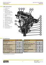
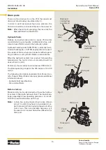
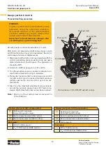
Controls and gauge ports
WARNING
In order to prevent injury to the technician or the
bystanders during the adjustment procedure, all
hydraulic functions on the vehicle/machine should
be disabled (e.g. wheels raised off the ground,
work functions disconnected).
Avoid fast forward/reversed changes that can
damage the synchronizing shaft.
Airbleed
port
Port X4
Main port A
Main port B
Port X1
Port X2
Gauge/pilot ports (EO/EP control):
X1
Setting piston pressure
(large setting piston area)
X2
Servo supply pressure (after orifice)
X4
Servo supply pressure (before orifice)
Port sizes:
–
M14x1.5 (ISO version)
–
9
/
16
"-18 O-ring boss (SAE version).
Port locations - V16 -220/270 with EO/EP control.
Setting screw

