APPENDIX B
121
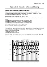
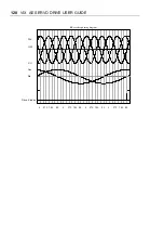
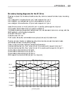
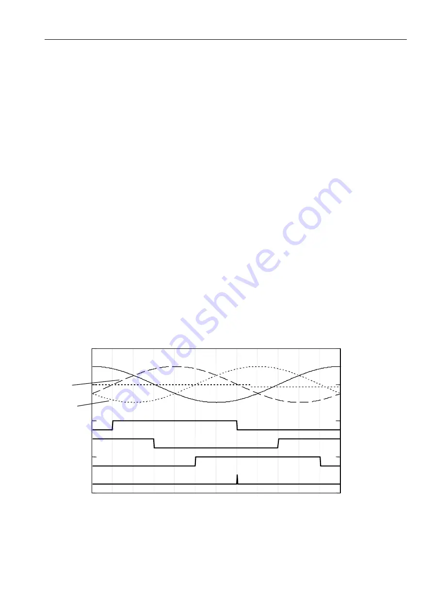
Encoder phasing diagrams for the IE Drive
Phasing is shown for clockwise rotation when the motor is viewed from the motor mounting
flange.
Line voltage W-V is defined as X1 pin 2 with respect to X1 pin 3
Line voltage V-U is defined as X1 pin 3 with respect to X1 pin 4
Line voltage U-W is defined as X1 pin 4 with respect to X1 pin 2
IndexZ mark occurs (is “true”) when X2 pin1 is positive with respect to X2 pin 2
The position of the index mark is a system variable IX.
The default setting and expected requirement of a non standard motor is to comply with the
SME setting to avoid having to adjust IX.
For SME motors IX = 150
For BE motors IX = 90
For H series drives the commutation set up does not use the index mark
Positive encoder rotation is defined as when incremental encoder channel A leads
incremental encoder channel B by 90deg
There is only one index mark per mechanical revolution
Incremental channel A is “true” when X2 pin 8 is positive with respect to X2 pin 7
Incremental channel B is “true” when X2 pin 12 is positive with respect to X2 pin 11
Commutation channel A0 is at X2 pin 9
Commutation channel A1 is at X2 pin 13
Commutation channel A2 is at X2 pin 14
With respect to encoder GND (X2 pin 3 or X2 pin 6)
0
30
60
90
120
150
180
210
240
270
300
330
360
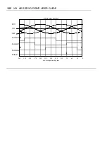
SME phasing diagram
electrical postion
d
W-V
V-U
U-W
CommA0
CommA1
CommA2
IndexZ
Summary of Contents for ViX250AE
Page 2: ......
Page 57: ...50 VIX AE SERVO DRIVE USER GUIDE...
Page 123: ...116 VIX AE SERVO DRIVE USER GUIDE...
Page 135: ......

