22
VIX AE SERVO DRIVE USER GUIDE
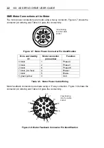
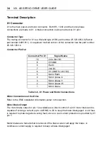
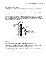
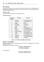
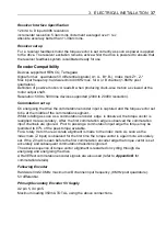
SMB Motor Connections at the Motor
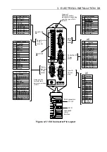
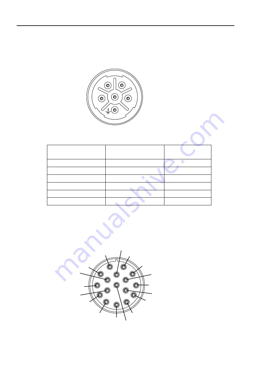
The motor power connections are made using a 6-way connector. Figure 3-7 shows the
connector pin lettering and Table 3-5 gives the connectivity.
1
2
4
3
5
6
View looking
into the cable
socket
Figure 3-7. Motor Power Connector Pin Identification
Drive end identity
X1
Motor connector
pin number
Function
4 black
1
Phase U
3 black
2
Phase V
2 black
6
Phase W
7 black (via fuse)
4
Brake+
1 black
5
Brake-
5 green/yellow
3
Gnd
Table 3-5. Motor Power Cable Wiring
Motor feedback connections are made using a 17-way connector. Figure 3-8 shows the
connector pin lettering and Table 3-6 gives the connectivity.
7
8
10
16
13
14
17
15
11
12
9
1
2
3
4
5
6
View looking
into the cable
socket
Figure 3-8. Motor Feedback Connector Pin Identification
Summary of Contents for ViX250AE
Page 2: ......
Page 57: ...50 VIX AE SERVO DRIVE USER GUIDE...
Page 123: ...116 VIX AE SERVO DRIVE USER GUIDE...
Page 135: ......

