3. ELECTRICAL INSTALLATION 29
Motor Related System Variables
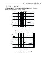
Two-system variables control the current supplied to the motor from the drive. Current
Clamp (CL) limits the current output of the drive to protect low current motors or to set a
particular torque level, and Peak Current (PC) can allow a controlled boost of motor current
when required.
CL can be set as a percentage (1 to 100%) of the peak drive current and once set drive
output current cannot be exceeded using any other command or system variable.
PC sets the scale factor (100 to 400%) that controls the ratio of maximum output current to
continuous output current of the drive. Servo motors can be overdriven for short periods to
provide extra torque. PC is calculated as follows:
PC = desired maximum drive current x 100
motor continuous stall current
A value of 300% is typically used for boosting servo motor performance.
Enter CL and PC values using EASI-V guided servo initialisation or directly, using the W
command.
Drive/Motor Overload
The ViX drive uses an I
2
t protection scheme that prevents excessive heat dissipation in the
drive and motor. Protection operates by monitoring the level of three separate dissipation
parameters and comparing them to their individual I
2
t thresholds. These dissipation
parameters are:
•
Motor I
2
T – protects the motor from drive output current above the rated motor current
that is applied for too long a time.
•
Moving I
2
T – protects the drive from output current while moving, that is above the rated
drive current for too long a time.
•
Stationary I
2
T – protects the drive from output current while stationary, that is above the
rated drive current for too long a time.
If any one of these monitored parameters exceeds the set I
2
t threshold, the drive current
folds back to 80% of the normal running continuous limit. The status LED will continuously
flash red and green and status bit 16 of the system variable ST will be set to ‘1’. The drive
output will remain at the 80% level for 30 seconds, after which the parameter that caused the
I
2
t threshold to be exceeded is re-tested. If the re-tested parameter has dropped in value by
50% or greater of its original fault level, the drive output is returned to its normal current
level. If the failing parameter is found to be still high (>50%) the drive output remains
restricted to its 80% value and continuous checking of the parameter is carried out until the
50% value is reached. When this happens, the drive returns to normal operation, the status
LED stops flashing and ST bit 16 is reset.
Summary of Contents for ViX250AE
Page 2: ......
Page 57: ...50 VIX AE SERVO DRIVE USER GUIDE...
Page 123: ...116 VIX AE SERVO DRIVE USER GUIDE...
Page 135: ......

