VIX AE SERVO DRIVE USER GUIDE
66
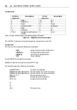
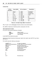
Connections
V
i
X X4
connector
Description
6K connectors
Description
1
Ana1+
3 - Drive
C
2
Ana1-
6 - Drive
Command -
3
0V
9 - Drive
Isolated Gnd
6
Fault
5 - Drive
Fault
9
A- out
3 - Encoder
A -
10
B- out
5 - Encoder
B -
11
Energise
7 - Drive
Shutdown (NO)
14
A+ out
2 - Encoder
A +
15
B+ out
4 - Encoder
B +
Table 4-8. Velocity/Torque Mode Connections
*
Pins 13 and 14 on the 6K DRIVE connector should be connected together.
The CNTRL-P terminal on the 6K should be connected to +24V DC.
Velocity Mode Commands
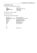
For the ViX drive issue the following commands:
1MV
;Mode Velocity
1W(ES,0)
;Energise input active level
1SV
;Save settings
A valid MOTOR command is required.
At least some feed-forward and velocity gain needs to be used to tune the PIVF loop, that is
GF=GV=5.0.
For the 6K4 issue the following commands:
AXSDEF1111
All axes are steppers
ERES8000,8000,8000,8000
Should match V
i
X motor resolution
DRFLVL1111
Drive fault active level
DRFEN1
Enable drive fault detection
LH0,0,0,0
Disable limits (optional)
TGAIN
Read all gains
SGP
Set proportional gain
SVG
Set velocity gain
A
V
D
GO1
Execute move
Summary of Contents for ViX250AE
Page 2: ......
Page 57: ...50 VIX AE SERVO DRIVE USER GUIDE...
Page 123: ...116 VIX AE SERVO DRIVE USER GUIDE...
Page 135: ......

