
Variable displacement pump
Series VP1-095 / -110
/
-130
Bulletin MSG30-8214-INST/UK
Installation information
2
Parker Hannifin
Pump & Motor Division Europe
Trollhättan, Sweden
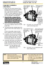
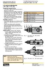
Inlet (suc-
tion) port;
the suction
fitting must
be ordered
separately
(see pg. 7)
Outlet (pressure)
port (BSP 1”)
Arrow indicates
pump rotation
(right hand
shown)
Fig. 1. VP1-095 / -110 / -130 main ports;
right hand rotating pump.
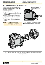
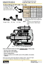
Fig. 2. VP1-095 / -110/ -130 main ports; left
hand rotating pump.
Inlet (suction) port;
the suction fitting
must be ordered
separately (see
pg. 7)
Outlet
(pressure)
port
(BSP 1”)
Arrow indicates
pump rota-
tion (left hand
shown)
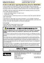
Port T
(BSP ¼”)
2 x M12
depth 17
to attach
support
device
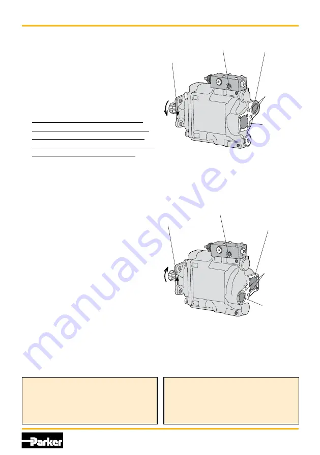
2 x M12
depth 17
to attach
support
device
Important installation
information
1
. Make sure max input torque and max
bending moment of the PTO (including
the VP1 pump) are not exceeded.
Also, make sure the direction of rotation
of the VP1 pump correspond to the PTO,
and that pump and PTO specifications
are not exceeded in the application.
2
. When VP1-095, -110 and -130 is as-
sembled to an engine PTO make sure
that the pump isn’t overheated in the
off-load mode. For more information, see
page 4, BPV-VP1 unloading valve.
3
. Never use excessive force when install-
ing a gear, coupling or sleeve on the VP1
pump shaft.
4
. The pump should be installed below the
lowest oil level in the reservoir (fig. 6, pg.
5);
if this is not possible, please contact
Parker Hannifin for further information.
5
. A separate drain line must be installed
between the control drain port T and the
reservoir (refer to fig. 6, pg. 5); connect
the drain line directly to the oil cooler (if
the hydraulic system is so equipped).
6
. A pressure relief valve is recommended
in the outlet (pressure) line from the
pump; it should be set 15–20 bar higher
than max pressure setting of the pump.
Example: The main pressure relief
valve located in the direc-
tional control valve.
Port T
(BSP ¼”)
NOTE:
- The suction fitting must be orde-
red separately (refer to
pg. 7
)
-
VP1-095 / -110 / -130 installation
on a PTO: please refer to page 3
for information.
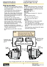
NOTE:
Always run a function,
after adjusting the standby pres-
sure or the max pressure setting,
before you read the value.


