Variable displacement pump
Series VP1-095 / -110
/
-130
Bulletin MSG30-8214-INST/UK
Installation information
3
Parker Hannifin
Pump & Motor Division Europe
Trollhättan, Sweden
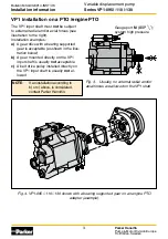
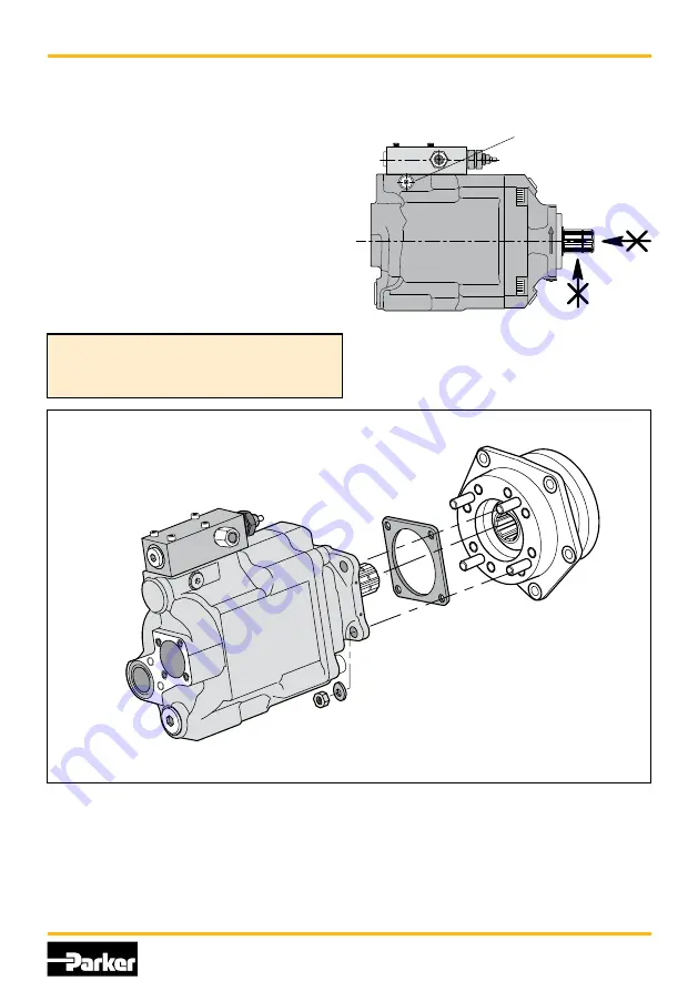
Fig. 4. VP1-095 / -110 / -130 shown with a bearing supported gear on an engine PTO
adapter (example).
VP1-095_no_shaft_loads.ai
Leif A./11-02-04
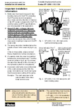
The VP1 input shaft must
not
be subject
to external radial and/or axial forces (see
illustration to the right).
Installation examples:
a)
A gear drive with a bearing supported
gear is acceptable (as shown in the illus-
tration below)
b)
A gear mounted directly on the VP1
input shaft is usually
not
acceptable
c)
A belt drive pulley installed directly on
the VP1 input shaft is usually
not
al-
lowed
Fig. 3. Usually, no external radial and/or
axial forces are allowed on the VP1 shaft
VP1 installation on a PTO /engine PTO
NOTE
:
If an installation according to
b) or c) above, is considered,
contact Parker Hannifin.
Gauge port
M
(BSP
1
/
4
”);
system high pressure


