background image

Variable displacement pump

Series VP1-095 / -110


/


-130

Bulletin MSG30-8214-INST/UK

Installation information

5

Parker Hannifin

Pump & Motor Division Europe

Trollhättan, Sweden

VP1_095_below_tank_ny2.ai

Leif A./07-03-29

Start-up procedure

-   Make sure the entire hydraulic system is 

as clean as possible before filling it with a 

recommended fluid.

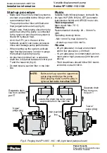
-   The pump must be filled with fluid and 

then purged before start-up (fig. 6). 

   Please note, that purging should only be 

performed when the pump is connected 

to the reservoir and the entire system is 

filled with hydraulic fluid.

-   Air in the VP1 (or in the rest of the 

hydraulic system) can cause excessive 

noise and damage pump performance.

-   When starting up the system, activate 

high flow/low pressure in order to purge 

the hydraulic system properly.

-   As previously pointed out, a separate 

drain line is required between control port 

T and the reservoir (fig. 6).

-   Do 

not

 install a suction filter in the inlet 

line.

Fluids

Suitable fluids: Mineral based, hydraulic flu-

ids type HLP (DIN 51524), ATF (automatic 

transmission fluids) and API/CD motor oils. 

Fluid temperature

Main circuit: Max 75 °C.

Viscosity

Recommended viscosity: 20 – 30 mm

2

/s 

(cSt). 

Operating viscosity limits:
- Min 10 mm

2

/s; max 400 mm

2

/s

- At start-up: max 1000 mm

2

/s.

Filtration

-   25 µm (absolute) in clean environment 

and/or low pressures (< 200 bar)

-   10 µm (absolute) in contaminated environ-

ment and/or high pressures (200 bar and 

above).

-   Fluid cleanliness should follow ISO stand-

ard 4406, code 20/18/13.
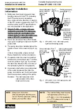
NOTE:

  Before start-up, open the uppermost  


purge plug and purge the pump. 


After purging, make sure the plug is  


tightened 

but not to more than 30 Nm.
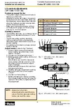
Inlet (suction)

 line 

Separate drain 

line from con-

trol port T

Locate the drain line as far away 

as possible from the inlet line

Separa

te drain 

line from con

trol 

port T

’Upper’

purge plug

Fig. 6. Purging the VP1-095 / -110 / -130 (right hand pumps shown)

’L

ower’

purge

 plug

Summary of Contents for VP1-110 Series

Page 1: ...letin MSG30 8214 INST UK Installation and Startup Manual Hydraulic Pumps SeriesVP1 095 110 130 Effective March 01 2018 Supersedes September 05 2017 Visit our homepage for additional support parker com pmde ...

Page 2: ...pplication 2 When VP1 095 110 and 130 is as sembled to an engine PTO make sure that the pump isn t overheated in the off load mode For more information see page 4 BPV VP1 unloading valve 3 Never use excessive force when install ing a gear coupling or sleeve on the VP1 pump shaft 4 The pump should be installed below the lowest oil level in the reservoir fig 6 pg 5 if this is not possible please con...

Page 3: ...ial forces see illustration to the right Installation examples a A gear drive with a bearing supported gear is acceptable as shown in the illus tration below b A gear mounted directly on the VP1 input shaft is usually not acceptable c A belt drive pulley installed directly on the VP1 input shaft is usually not al lowed Fig 3 Usually no external radial and or axial forces are allowed on the VP1 sha...

Page 4: ...lation on an engine PTO BPV VP1 unloading valve The BPV VP1 unloading valve is utilized in hydraulic systems where the pump is in constant operation The valve protects the pump from being overheated in the off load mode by allow ing a small flow through the pump When load sensing valve function is engaged the bypass flow is cut off as port X is being pressurized The valve will also de air the suct...

Page 5: ...ired between control port T and the reservoir fig 6 Do not install a suction filter in the inlet line Fluids Suitable fluids Mineral based hydraulic flu ids type HLP DIN 51524 ATF automatic transmission fluids and API CD motor oils Fluid temperature Main circuit Max 75 C Viscosity Recommended viscosity 20 30 mm2 s cSt Operating viscosity limits Min 10 mm2 s max 400 mm2 s At start up max 1000 mm2 s...

Page 6: ...ditional information please contact Parker Hannifin Adjustments refer to fig 7 below 1 System high pressure adjustment screw factory set at 350 bar 1 turn approx 140 bar 1 2 Counter nut for adjustment screw 1 3 Bushing basic valve setting factory set DO NOT TOUCH Note Before you read the measured value always activate and run a func tion after you have made the adjust ment of settings Adjust stand...

Page 7: ... 21 2 378 0634 90 21 2 378 1980 Straight 2 3 378 3523 45 2 3 378 3367 90 2 3 378 8690 2 Utilize the 3 fitting when the reservoir is below the pump or flow is larger than 140 l min NOTE A fitting is not included with the pump it must be ordered sepa rately VP1_095_cross_section u ai Leif A 07 03 14 If any oil should come out of the indication hole on the pump Stop the system immediately Determine t...

Page 8: ...INJURY AND PROPERTY DAMAGE This document and other information from Parker Hannifin Corporation its subsidiaries and author ized distributors provide product or system options for further investigation by users having technical expertise The user through its own analysis and testing is solely responsible for making the final selection of the system and components and assuring that all performance ...

Reviews: