Digital Power Amplifier
Series VRD350 and VRD355
Installation Manual
33
IA VRD UK.INDD RH 02.06
Parker Hannifin GmbH & Co. KG
Hydraulic Controls Division
4. Operating and Error Messages
Supply
The LED „24V“ lights up when the supply voltage
is present.
4.1. Enable
• After the enable signal has been applied to
terminal 8d, the LED "ENABLE" flashes for the
period of the time delay set in parameter E9.
• Once the time delay elapses, the flashing signal
becomes a continuous signal and the output
stages are enabled.
• The enable input is electrically isolated by
means of an opto-coupler.
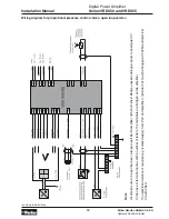
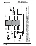
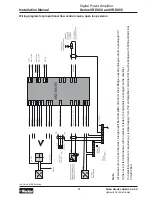
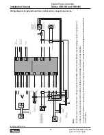
• If no electrical isolation is required, terminal 2d
must be bridged with terminal 26d and terminal
32z must be bridged with terminal 32bd of the
unit by the customer.
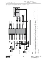
4.2. RESET RAMP
A 24V signal at the Reset Ramp input (terminal
18z) immediately sets the ramp function generator
to zero. Once the signal is switched off, the ramp
function generator starts again from zero. The
preset time constant (S5 to S8) is then used to run
up the preset command signal. The Reset Ramp
input is galvanically isolated via opto-couplers (see
figure page 9).
4.3. Malfunction and Error Messages
• The current in the output stages is monitored
in the amplifier. If the total current exceeds a
specific limit, an electronic cut-out responds and
switches the output stages off. At the same time,
the signal at the ‘Error’ output (terminal 14d) is
set to 0V (cable fracture detection).
• Malfunction signals are not cleared by switch-
ing off the supply voltage, but by removing the
enable signal. Otherwise error diagnosis on the
basis of error messages is no longer possible.
• The fault output is electrically isolated by an
opto-coupler and short circuit protected by a
PTC resistor
• If no electrical isolation is required, terminal
32z must be bridged with terminal 32bd by the
customer.
Display Fault
--1
Programming error E2
--2
Transducer cable fracture (only if E12 = 1)
--3
Excess current cut-out active
--4
A/D-converter failure
--5
Cable fracture detection not possible
Error is canceled by releasing arrow keys
--6
No valid data in ABG35S or incorrect
software version
--7
Read error when reading ABG35S
--8
Write/read error (verify)
Possible Error Messages
E2 Enable conditions
LED >>10V
0
Sum S1 to S4 and SW5 and
off
SW6 <
9.95
V
0
Sum S1 to S4 and SW5 and
on
SW6 >
9.95
V
1...4
U12 <
9.95
V
off
1...4
U12 >
9.95
V
on
Warning >>10V
The following conditions apply for this LED:


