background image

46

MSC4000 - MSC15000 USER MANUAL

Summary of Contents for -W4P

Page 1: ...Magnum Refrigerated Air Dryers Models MSC4000 MSC15000...

Page 2: ...e operating conditions and may void warranty For additional information refer to this manual or contact the factory for recommendations Please have the dryer serial number and model ready when contact...

Page 3: ...emperature Sensors 21 Factory Settings 22 Variable Speed Drive 24 4 3 Trending 25 Trend Elements 26 User Controls 27 4 4 I O Screens 28 Input States 28 Ouput States 30 4 5 Sensors 31 4 6 Service Scree...

Page 4: ...em must be provided to eliminate re circulation of hot atmospheric air With air cooled dryers high ambient temperatures affect the outlet dewpoint of the dryer The unit must not operate in an ambient...

Page 5: ...n box All units must be externally grounded to protect against severe electrical shock Check for correct voltage and phase at electrical connection box Install a fused disconnect switch near the dryer...

Page 6: ...ubesheet into one of the evaporator tubes Note When installing the probe use a thread lock sealant on the brass and steel threads If probe is not installed correctly it WILL result in damage to the ev...

Page 7: ...enser water shell START THE DRYER BEFORE SUPPLYING AIR CAUTION 1 Press the RUN button to start the dryer See description of Oil Management Mode in Section 7 1 if the system goes into oil management mo...

Page 8: ...F with air compressor 8 Restart dryer using this procedure after maintenance power outage or prolonged periods of shutdown 2 hours or more Note The refrigerant compressor may require additional oil ad...

Page 9: ...9 MSC4000 MSC15000 USER MANUAL Start Up Checklist...

Page 10: ...________________________________________ _______________________________________________________________ _______________________________________________________________ _______________________________...

Page 11: ...11 MSC4000 MSC15000 USER MANUAL...

Page 12: ...auto select mode Load Unload Mode Touch to switch to Load Unload Mode Cycling Mode Touch to switch to Cycling Mode 6 Alarm Keys M Alarm Reset Key Touch to reset all active alarms Alarm Silence Key To...

Page 13: ...dryer output will be reduced DRYER NOT CONFIGURED The dryer must be configured before it will run ACTIVE ALARMS Refer to the Alarms Section for alarm messages displayed on this line 2 State Message L...

Page 14: ...f the compressor is bypassed 3 Fan Indicators Air Cooled Models only Fan State The fan icon will turn on if any of the fans are running Multi Fan indicators 1 through 3 On dryers with more than 1 fan...

Page 15: ...cess the states of the PLC Inputs and Outputs 5 Service Icons Touch for access to service functions 6 Support Icon Touch for access to dryer and support information 7 Hide Menu Icon Touch to hide the...

Page 16: ...e Warning M Setting Touch to adjust the High Inlet Pressure Warning threshold Enabled Disabled Touch to Disable or Enable the warning High Filter Pressure Warning M Touch to adjust the High Filter Pre...

Page 17: ...tch is closed or not Drain Cycle Interval M Set the number of seconds between drain opening for drains which are running in Timed Drain mode Drain On Duration M Set the number of seconds that the drai...

Page 18: ...dically output the compressor at 100 to ensure that there is enough oil getting back to the compressor under low load conditions Pressure Units M Select units for pressure values used for all displays...

Page 19: ...sensor maximum 4 characters Sensor Range M Enter the minimum and maximum limits of the sensor range 32768 to 32767 units for sensor one 3276 8 to 3276 7 units for sensor one Offset Correction M Enter...

Page 20: ...Sensor Range S Enter the minimum and maximum limits of the sensor range Offset Correction S Enter an offset value for the sensor range Pressure Units M Select units for pressure values used for all di...

Page 21: ...Correction S Use to correct the offset for each temperature sensor Temperature Units M Select units for temperature values used on all displays and logs Temperature Sensors M Supervisor level access r...

Page 22: ...rs with 2 or more active compressors These settings are to be changed only by the Dryer Manufacturer s Factory or Service Personnel and are included here for reference only Compressor Off Offset F In...

Page 23: ...s at when the Store Factory Settings key was last pressed Variable Speed Drive Settings key S On dryers with a variable speed drive touch this key to troubleshoot operation related to the compressor d...

Page 24: ...this to adjust the integral response of the dryer PID Filter TC F Use this to filter the dewpoint input PID Max Suction TC F This setting sets the upper suction pressure limit for the dryer The contr...

Page 25: ...ows Dewpoint Output Load and VSD output VSD models only REFRIGERATION Shows Superheat and Refrigeration Temp Discharge Suction pressures SUCTION Shows Superheat and Refrigeration Temperature Suction p...

Page 26: ...Scale shows the scale for the corresponding colored data 3 Value box shows the value of the data at the cursor line 4 Time at cursor line displays the time of the data at the cursor line 5 Cursor line...

Page 27: ...pens a search window where a date and time can be entered Exporting data takes a very long time several minutes to an hour and will render the display unresponsive until the download is complete For t...

Page 28: ...28 MSC4000 MSC15000 USER MANUAL 4 4 I O Screens...

Page 29: ...ct drive compressors The fault relay is located on the starter over load for the corresponding compressor and must be reset at the overload module Variable Speed compressors Alarm relay is located on...

Page 30: ...der Unloader Banks A B ON indicates that compressor corresponding cylinder is unloaded Alarm Relay ON indicates that the alarm relay contacts are open The alarm relay is set for normally open or norma...

Page 31: ...SC15000 USER MANUAL 4 5 Sensors The Sensors screen displays all of the pressure and temperature sensor values in graphical form Also displays the values of the optional user sensor inputs shown in are...

Page 32: ...ethod of rebooting the display panel should it be necessary An alternate method it to press the reset button on the bottom of the control box Exit to System S Exits the application so that system leve...

Page 33: ...e service timer and corresponding alarm Service Timer Setting M Set the number of days between service internals from 0 to 365 days Set to 0 to see effects of alarm Disable Service Timer M Touch to di...

Page 34: ...figured by touching the DST CFG key System time conflict Warning Note Changing the real time clock to a time that is prior to the latest logged value will suspend trend user interaction until the cloc...

Page 35: ...35 MSC4000 MSC15000 USER MANUAL Reference Guide...

Page 36: ...36 MSC4000 MSC15000 USER MANUAL...

Page 37: ...37 MSC4000 MSC15000 USER MANUAL...

Page 38: ...38 MSC4000 MSC15000 USER MANUAL...

Page 39: ...39 MSC4000 MSC15000 USER MANUAL 4 7 Support Screen Only users with Factory or Service level password can change this information...

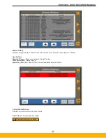
Page 40: ...8 Alarm Screens Alarm indicators codes 101 through 199 will display in RED Warning Indicators code 201 through 299 will display in YELLOW Touch the indicator will display corresponding troubleshootin...

Page 41: ...l active alarms Alarm History Displays a log of all alarm and event activity since the last time the history log was cleared User Buttons Page Up Down Move up and down through the log Clear History M...

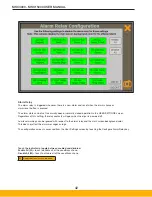
Page 42: ...n when the dryer is powered off Low level warnings can be ignored with respect to the alarm relay and the main screen background color This does not affect the alarm messages or logs The configuration...

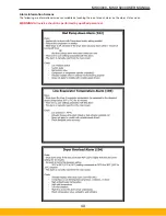
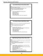
Page 43: ...000 USER MANUAL Alarm Information Screens The following are informational screens available by touching the icon for each alarm on the alarm state screen WARNING All service should be performed by qua...

Page 44: ...44 MSC4000 MSC15000 USER MANUAL...

Page 45: ...45 MSC4000 MSC15000 USER MANUAL...

Page 46: ...46 MSC4000 MSC15000 USER MANUAL...

Page 47: ...47 MSC4000 MSC15000 USER MANUAL...

Page 48: ...48 MSC4000 MSC15000 USER MANUAL...

Page 49: ...49 MSC4000 MSC15000 USER MANUAL...

Page 50: ...50 MSC4000 MSC15000 USER MANUAL...

Page 51: ...51 MSC4000 MSC15000 USER MANUAL...

Page 52: ...y shut down Rebooting the display panel via the Service menu or via Modbus register 40101 will restore the VNC Server after reboot Serial Modbus RTU Port The serial port is located along the bottom ed...

Page 53: ...IP Settings ETHERNET TROUBLESHOOTING If the panel fails to connect then either there is a problem with the connection or one of the settings From a computer on the same network ping the dryer s addre...

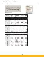
Page 54: ...32C 7 SG Signal Ground 5V RS232C 8 DCD Data Carrier Detect Output RS232C 9 10 11 12 TXDA Transmit Data Output RS422 RS485 13 TXDB Transmit Data Output RS422 RS485 14 RTSA Request to Send Output RS422...

Page 55: ...or 0 1x0022 Alarm State 105 Low Refrigeration Pressure 1 or 0 1x0023 Alarm State 107 High Refrigeration Pressure 1 or 0 1x0024 Alarm State 202 Low Inlet Air Pressure 1 or 0 1x0025 Alarm State 203 High...

Page 56: ...e Sensor Fault 1 or 0 1x0069 Alarm State 141 Dewpoint Sensor Fault 1 or 0 1x0070 Alarm State 142 Ambient Temperature Sensor Fault 1 or 0 1x0071 Alarm State 235 Aux User Sensor Input 1 Fault 1 or 0 1x0...

Page 57: ...itoring System Alarm 1 or 0 1x0113 Input State Compressor 4 Overload Switch 1 or 0 1x0114 Input State Compressor 4 Low Oil Pressure 1 or 0 1x0115 Input State Compressor 4 Oil Monitoring System Alarm 1...

Page 58: ...ed 3x0028 Reserved 3x0029 Reserved 3x0030 Reserved 3x0031 Reserved 3x0032 Dryer Load Percent 0 to 120 0 to 120 3x0033 VSD Output 0 30Hz 255 60Hz 0 to 255 3x0034 Output Capacity 0 to 100 0 to 100 4x000...

Page 59: ...to 1000 psi 4x0044 Calibration Sensor Max Set Discharge Pressure 1000 to 1000 psi 4x0045 Not used 4x0046 Not used 4x0047 Calibration Sensor Max Set User Sensor 1 32678 to 32767 4x0048 Calibration Sen...

Page 60: ...r 0 4x0096 Control Setting Multiple Compressor Compressor 2 Enable 1 or 0 4x0097 Control Setting Multiple Compressor Compressor 3 Enable 1 or 0 4x0098 Control Setting Multiple Compressor Compressor 4...

Page 61: ...stem Alarm Enable 1 or 0 4x0112 Alarm Setting Aux Sensor 1 Low Alarm Enable 1 or 0 4x0113 Alarm Setting Aux Sensor 1 High Alarm Enable 1 or 0 4x0114 Alarm Setting Aux Sensor 2 Low Alarm Enable 1 or 0...

Page 62: ...There are five inputs on the PLC dedicated to using external switches or relays to control the dryer operation These inputs require a 120VAC signal Refer to the dryers wiring schematic for details Al...

Page 63: ...s required to clean the tubes These cleaning systems utilize a flexible shaft which rotates a brush as it is fed down the tube they can also simultaneously flush out the tubes with water There is a wi...

Page 64: ...eck Fan Control Switches AC units Check Check Check Compressor Oil Level Check Check Check Check Drain Solenoid Check Clean Check Clean Check Clean Oil Separator Element Check change at 20 PSID Oil se...

Page 65: ...ry 4 Check actual oil pressure at the com pressor with refrigeration gauges Replace switch if necessary 5 If surge tank sightglass is normal should be 1 4 1 2 full in loaded state add oil to compresso...

Page 66: ...nd all valves Using the Emergency stop switch for other than emergency situations may result in voiding the warranty of the dryer PRESSURE SENSOR ALARM WARNING 131 132 241 242 Rules Fault if pressure...

Page 67: ...1 Inlet air temperature too high 1 Clean air compressor and or improve room ventilation HIGH CONDENSER TEMP 205 Rules Warning if the condenser temperature ambient water rises above the setting for 5 m...

Page 68: ...below the set point for 5 minutes Pressing alarm reset will reset the alarm and alarm timer Causes 1 Plant air output pressure set too high 1 Check plant compressed air system SERVICE TIMER WARNING 20...

Page 69: ...les Causes Possible Remedy AUXILIARY ANALOG INPUT WARNING 231 236 Rules There are 2 separate auxiliary 4 20mA inputs for connecting flow meters or other user devices Refer to User Sensor Settings scre...

Page 70: ...started this mode will prevent the compressor from running with low oil for more than two minutes after the system has been turned back on Instead it times out after two minutes and forces the dryer i...

Page 71: ...il is added at the factory to compensate for the migration with the refrigerant If a compressor is replaced remove the drain plug from the evaporator shell to drain any excess oil trapped If that isn...

Page 72: ...gerant charge Ambient Tempera ture Air Inlet Temperature Cooling Water Temperature Cooling Water Req d 85 F Condenser Heat Rejection MAWP Connections Air in out Water in out Drain Lbs Min Max Min Max...

Page 73: ...9 200 21 9 30 MSC15000 A4P 460 3 60 2 40 73 9 350 6 21 1 5 167 3 225 21 9 30 Model Refrigerant charge Ambient Temperature Air Inlet Temperature Condenser Heat Rejection MAWP Connections Air in out Dr...

Page 74: ...harge Ambient Temperature Air Inlet Temperature Cooling Water Temperature Cooling Water Req d 85 F Condenser Heat Rejection MAWP Connections Air in out Water in out Drain Lbs Min Max Min Max Min Max G...

Page 75: ...0 7 150 21 9 30 MSC15000 A4PV 460 3 60 2 35 64 4 275 6 3 5 1 5 145 9 200 21 9 30 Model Refrigerant charge Ambient Temperature Air Inlet Temperature Condenser Heat Rejection MAWP Connections Air in out...

Page 76: ...125 A1 DP20125 A1 DP20125 A1 DP20125 A1 DP20125 A1 DP20125 A1 Fan motor x2 DP205 21 1M 1 x2 DP205 21 1M 1 x2 DP205 21 1M 1 x3 DP205 21 1M 1 x4 DP205 21 1M 1 x6 DP205 21 1M 1 x6 DP205 21 1M 1 Fan blade...

Page 77: ...315 C Liquid line drier core A C x2 DP28315 C x2 DP28315 C x2 DP28315 C x4 DP28315 C x4 DP28315 C x4 DP28315 C x4 DP28315 C Suction filter core W C DP28315 B DP28315 B A DP28315 B x2 DP28315 B x2 DP28...

Page 78: ...overload W C ES0022 1 ES0025 1 ES0030 1 ES0040 1 ES0050 1 x2 ES0033 1 x2 ES0035 1 Compressor starter overload A C ES0025 1 ES0030 1 ES0035 1 ES0050 1 x2 ES0030 1 x2 ES0035 1 x2 ES0040 1 Control trans...

Page 79: ...0125 A DP20125 A DP20125 A DP20125 A Refrigerant relief valve A C DP20125 A1 DP20125 A1 DP20125 A1 DP20125 A1 DP20125 A1 DP20125 A1 DP20125 A1 Fan motor x2 DP205 21 1M 1 x2 DP205 21 1M 1 x2 DP205 21 1...

Page 80: ...witch DP40210 PLC DP5300 PLC HMI DP5300 HMI POWER SUPPLY TP2500 PS 24LP FUSE 1 8 AMP EF0025 TD FUSE 1 AMP EF0100 2 TD FUSE 2 AMP EF0200 2 TD MEMORY CARD TP2681 MEM Input Module NTC 2008SC NTC Input Mo...

Page 81: ...switch A C ES3030 ES3050 ES3060 ES3200 Variable Speed Drive W C EV0015 D 1 EV0300 1 EV0350 1 EV0400 1 TBD TBD x2 EV0350 1 Variable Speed Drive A C EV0020 D 1 EV0350 1 EV0350 1 TBD TBD x2 EV0350 1 Cont...

Page 82: ...82 MSC4000 MSC15000 USER MANUAL 10 Associated Drawings...

Page 83: ...83 MSC4000 MSC15000 USER MANUAL...

Page 84: ...84 MSC4000 MSC15000 USER MANUAL...

Page 85: ...85 MSC4000 MSC15000 USER MANUAL...

Page 86: ...86 MSC4000 MSC15000 USER MANUAL...

Page 87: ...87 MSC4000 MSC15000 USER MANUAL...

Page 88: ...88 MSC4000 MSC15000 USER MANUAL...

Page 89: ...89 MSC4000 MSC15000 USER MANUAL...

Page 90: ...90 MSC4000 MSC15000 USER MANUAL...

Page 91: ...91 MSC4000 MSC15000 USER MANUAL...

Page 92: ...92 MSC4000 MSC15000 USER MANUAL...

Page 93: ...93 MSC4000 MSC15000 USER MANUAL...

Page 94: ...94 MSC4000 MSC15000 USER MANUAL...

Page 95: ...95 MSC4000 MSC15000 USER MANUAL...

Page 96: ...96 MSC4000 MSC15000 USER MANUAL...

Page 97: ...97 MSC4000 MSC15000 USER MANUAL...

Page 98: ...1 BLK 1 BLK 1 3 1 3 2 WHT 2 WHT 3 1 2 2 2 HP SENSE OL SENSE 20 I 00 COM0 PLCC WHT 2 LP SENSE 20 RED RED 38 1 2 BLK BLK BLK BLK BLK END 2 FILTER DRAIN SWITCH SENSE SUMP DRAIN SWITCH SENSE 39 40 BLK HE...

Page 99: ...1 3 1 3 1 WHT RED RED 2 WHT 2 WHT WHT 1 BLK 1 BLK 1 BLK 1 3 1 3 2 WHT 2 WHT 3 1 2 2 2 HP SENSE OL SENSE 20 I 00 COM0 PLCC WHT 2 LP SENSE 20 RED RED 38 1 2 BLK BLK BLK BLK BLK BLK END 2 FILTER DRAIN SW...

Page 100: ...LCC WHT 2 RED LOW OIL PRESSURE 2 3 1 3 1 3 1 3 1 3 1 3 1 3 1 3 1 3 1 3 1 WHT RED RED 2 WHT 2 WHT WHT 1 BLK 1 BLK 1 BLK 1 3 1 3 2 WHT 2 WHT 3 1 2 2 2 HP SENSE OL SENSE 20 I 00 COM0 PLCC WHT 2 LP SENSE...

Page 101: ...SENSE 20 RED RED 38 1 2 BLK BLK BLK BLK END 2 FILTER DRAIN SWITCH SENSE SUMP DRAIN SWITCH SENSE 39 40 BLK HEATER 140W BLK BLK LOAD L N G LINE L N 5 6 4 2 DV1 HMI PE N L WHT 7 6 6 SW2 HMI RESET RED BL...

Page 102: ...2 HP SENSE 20 I 00 COM0 PLCC WHT 2 LP SENSE 20 RED RED 38 1 2 BLK BLK BLK BLK BLK END 2 FILTER DRAIN SWITCH SENSE SUMP DRAIN SWITCH SENSE 39 40 BLK HEATER 140W BLK BLK LOAD L N G LINE L N 5 6 4 2 DV1...

Page 103: ...HP SENSE 20 I 00 COM0 PLCC WHT 2 LP SENSE 20 RED RED 38 1 2 BLK BLK BLK BLK BLK BLK END 2 FILTER DRAIN SWITCH SENSE SUMP DRAIN SWITCH SENSE 39 40 BLK HEATER 140W BLK BLK LOAD L N G LINE L N 5 6 4 2 D...

Page 104: ...BLK 1 BLK 1 3 1 3 2 WHT 2 WHT 2 2 2 HP SENSE 20 I 00 COM0 PLCC WHT 2 LP SENSE 20 RED RED 38 1 2 BLK BLK BLK BLK BLK BLK BLK END 2 FILTER DRAIN SWITCH SENSE SUMP DRAIN SWITCH SENSE 39 40 BLK HEATER 14...

Page 105: ...HT 2 WHT WHT 1 BLK 1 BLK 1 BLK 1 3 1 3 2 WHT 2 WHT 2 2 2 HP SENSE 20 I 00 COM0 PLCC WHT 2 LP SENSE 20 RED RED 38 1 2 BLK BLK BLK BLK BLK BLK BLK BLK END 2 FILTER DRAIN SWITCH SENSE SUMP DRAIN SWITCH S...

Page 106: ...106 MSC4000 MSC15000 USER MANUAL 11 Maintenance Charts Maintenance Log Date Service Performed Parts Replaced Initials...

Page 107: ...__________ Ease of Start Up ______________________ Product Quality _______________________ Technical Assistance ___________________ Clarity of Instruction Warranty Manual _____ Final Operation Check L...

Page 108: ...108 MSC4000 MSC15000 USER MANUAL...

Page 109: ...109 MSC4000 MSC15000 USER MANUAL...

Page 110: ...rations Etten Leur Netherlands 31 76 508 5300 www parker com dhfns Hiross Zander Essen Germany 49 2054 9340 www parker com hzfd Padova Italy 39 049 9712 111 www parker com hzfd Engine Filtration Water...

Reviews: