background image

XRF Analyser Manual

8

Instrument set-up

Warning! It is critically important that the XRF Analyser is connected to the local 
mains power supply using the power adaptor and cable provided. Damage to 
internal circuitry caused by accidental use of the incorrect power supply is not 

covered by the warranty.

For best results, the XRF Analyser should be operated:

• 

On a flat, level surface such as a workbench or a desk.

• 

In temperature-stable environments.

• 

Away from drafts and heat sources such as air conditioning or heaters.

• 

 Away from strong magnetic fields, such as large electronic motors or generators, 
power transformers, loudspeakers or microwave ovens (these can even affect the 
instrument through walls).

 Before each use of the XRF instrument, a series of safety checks should be   
 carried out to ensure safety features are functional. This will likely be a requirement  
 of local regulations – see section 4. At a minimum, these checks should include:

• 

Visual checks for damage to the XRF exterior

• 

Visual check for cracks of the glass lid.

• 

Check the lid interlock - the lid must only open by pressing the button.

10 

Sample preparation

10.1 

Sample handling

Please read this section to familiarise yourself with sample preparation before using the 
XRF Analyser for the first time. 

In order to ensure a reliable measurement, the following steps should be taken to ensure 
that the measured sample is representative of the main body of fluid: 

• 

 Any containers used to store or collect fluid samples should be clean and free of 
contamination before use.

• 

The sample cups themselves should be kept in a clean dry environment.

• 

Fluid samples should be mixed thoroughly by shaking or stirring. 

• 

 Any air bubbles introduced during homogenisation should be allowed to disperse 
before dispensing the fluid into an XRF sample cup.

Summary of Contents for XRF

Page 1: ...XRF Analyser Instruction manual...

Page 2: ...XRF Analyser Manual...

Page 3: ...n 7 8 Spares consumables 7 9 Instrument set up 8 10 Sample preparation 8 10 1 Sample handling 8 10 2 Constructing and filling a sample cup 9 11 General Maintenance and cleaning 12 12 Method of operati...

Page 4: ...l be reduced to 0 5 The same regulations will continue to ensure that only fuel with a sulphur concentration of less than 0 1 can be burnt in designated Emission Control Areas ECAs such as the Baltic...

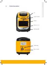
Page 5: ...XRF Analyser Manual 3 3 Product description Lid Open lid button Screen Power on off Warning lights USB socket Power socket...

Page 6: ...radiation safety rules set out by the UK Maritime and Coastguard Agency MGN451 covers the risk of radiation exposure on board ships This document specifically says that the Ionising Radiations Regula...

Page 7: ...ially the lid interlock lid release button and lights of the analyser prior to use Prepare local rules that require the unit to be returned in the event of suspected damage Maintain the analyser in li...

Page 8: ...accepted laboratory and statistical techniques is actually better than that provided in ISO 8754 Given this information the reproducibility of the unit should also be no worse than that stated in ISO...

Page 9: ...formation Please contact the manufacturer for service consumables spare parts and repairs Parker Hannifin Manufacturing Email kittiwakeinfo parker com 3 6 Thorgate Road Littlehampton BN17 7LU UK 8 Spa...

Page 10: ...safety features are functional This will likely be a requirement of local regulations see section 4 At a minimum these checks should include Visual checks for damage to the XRF exterior Visual check...

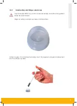
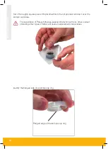
Page 11: ...Liquid samples MUST be put into a prepared sample cup before being placed inside the spectrometer Begin by setting a sample cup base on a flat surface Extract roughly 2 ml of sample fluid using one o...

Page 12: ...roll provided and lay it over the sample cup base The subsitution of Parker Kittiwake supplied Mylar film with any other product including other types of Mylar will cause measurement inaccuracies Iden...

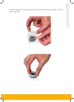
Page 13: ...XRF Analyser Manual 11 Press the flanged side of the sample cup ring down over the Mylar and snap it onto the sample cup base...

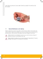
Page 14: ...of par ticularly stubborn stains can be assisted by the use of a mild hydrocarbon solvent such as isopropyl alcohol Other solvents or cleaning products may damage the instrument Replace Mylar film co...

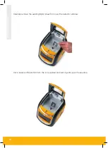
Page 15: ...ront of the unit to open the lid Undo the screw nearest the front of the XRF Analyser within the sample compartment Lift the screw completely out of the compartment and store safely Lift front end of...

Page 16: ...XRF Analyser Manual 14 Carefully remove the existing Mylar sheet from over the detector window Cut a square of Mylar film from the roll provided and rest it gently over the aperture...

Page 17: ...r serviceable parts and any attempt to dismantle the unit will invalidate the warranty Local regulation may require annual safety checks by a suitably qualified organisation such as a Radiation Protec...

Page 18: ...nual 16 12 Method of operation 12 1 Switching the unit on Prior to switching the unit on depress the oval silver button to open its lid Place a copper target centrally over the detector aperture and r...

Page 19: ...HOME screen to appear 12 2 Making a measurement Depress the oval silver button to open the lid and replace the copper target with the sam ple of interest prepared according to the instructions in sec...

Page 20: ...HOME screen if you wish to determine the sulphur content in a fuel or the LUBE button if you wish to determine the wear metal content in a lubricant The unit will present a START screen Press the PLA...

Page 21: ...ID table to reveal a soft keyboard that can be used to change their contents Press the ENTER key on the keyboard to complete any changes and then press OK to begin the test The screen will show the ti...

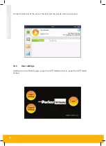
Page 22: ...RF Analyser Manual 20 An alert will sound at the end of the test and the results will be presented 12 3 User settings Starting from the HOME page press the SETTINGS button to reveal the SETTINGS scree...

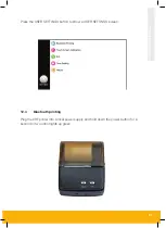
Page 23: ...ual 21 Press the USER SETTINGS button to show a USER SETTINGS screen 12 4 Bluetooth printing Plug the XRF printer into a local power supply and hold down the power button for a second or two until it...

Page 24: ...he device and then press CONNECT Once the XRF unit and printer are connected a blue tick will appear next to Qsprinter Press PRINT to print out the results of the most recent test or press RETURN to g...

Page 25: ...ger presses do not correspond with activation of the underlying button recalibration may be worthwhile From USER SETTINGS page press TOUCH SCREEN CALIBRATION Carefully press and briefly hold finger on...

Page 26: ...s the oval silver button on the XRF Analyser to open its lid Place a copper target centrally over the detector aperture and reclose the lid From the USER SETTINGS screen press the Init button A dialog...

Page 27: ...e USER SETTINGS screen 12 8 History From the USER settings screen press the HISTORY option to reveal the HISTORY screen The HISTORY screen lists out all of the test result files stored by the instrume...

Page 28: ...XRF Analyser Manual 26 After a few seconds the instrument will report that the files have been successfully exported...

Page 29: ...unit will ask for confirmation that you wish to switch to USB mode press YES Connect the XRF Analyser to a laptop or PC using the USB port on the rear of the instrument see Section 3 Windows will reco...

Page 30: ...ening the folder to view files option will reveal the contents of the device Open the Test history folder to reveal a file entitled All_HistoryRecord csv Double click on the All_HistoryRecord csv file...

Page 31: ...eleted from the HISTORY screen list by ticking them and pressing delete Press OK when the unit asks for confirmation Similarly all of the listed files can be removed from the HISTORY screen by pressin...

Page 32: ...he Parker Kittiwake XRF Analyser typically fall within the range 0 983 1 017 nineteen times out of twenty Of course this means that some measurements will fall outside this range Measurements of ident...

Page 33: ...o expel electrons from constituent atoms within a sample Atoms that lose an electron from an orbital close to their nucleus are particularly unstable and spontaneously rearrange their electronic struc...

Page 34: ...exactly the same lines In the most common design a cathode is electrically heated to stimulate the emission of electrons which are accelerated through an evacuated glass tube towards a metal anode The...

Page 35: ...result of photon absorption drift through the silicon under the influence of an electric field applied by a series of concentric reverse biased strips The electrons are eventually collected by a smal...

Page 36: ...o Equipment 2011 65 EU Restriction of the use of certain hazardous substances in electrical and electronic equipment The following harmonised and international standards have been applied EN 12100 201...

Page 37: ...XRF Analyser Manual 35...

Page 38: ...in Corporation MA K31464 KW Rev C Parker Kittiwake 3 6 Thorgate Road Littlehampton West Sussex BN17 7LU United Kingdom Tel 44 0 1903 731470 Fax 44 0 1903 731480 Email kittiwakeinfo parker com Web www...

Reviews: