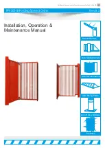
background image

Parking and access control equipment manufactured in the UK

PF9500 Bi-Folding Speed Gate

Rev:8.2

Installation, Operation &
Maintenance Manual

Manual Barriers

Auto Sliding barriers

Auto Bi-Fold barriers

Auto Rising Kerbs

Turnstiles

Auto Rising Bollards 

Summary of Contents for PF9500

Page 1: ...rol equipment manufactured in the UK PF9500 Bi Folding Speed Gate Rev 8 2 Installation Operation Maintenance Manual Manual Barriers Auto Sliding barriers Auto Bi Fold barriers Auto Rising Kerbs Turnstiles Auto Rising Bollards ...

Page 2: ...OVERVIEW 05 06 MANUAL RELEASE GUIDE 07 FIRST OPERATION MANOEUVER 08 PANEL USAGE GUIDE 09 TROUBLESHOOTING GUIDE 10 11 WIRING DIAGRAM 12 WIRING PRORAMMING DESCRIPTION 13 14 LOOP DETECTOR SETTINGS 15 TROUBLESHOOTING GUIDE 16 18 INSTALLATION COMMISSIONING CHECKLIST 19 SERVICE LOG 20 COMMISSIONING CERTIFICATE 21 ELECTRONICS CERTIFICATE 22 CERTIFICATE OF CONFORMITY 23 2 ...

Page 3: ...e the product and be dangerous The Company declines all responsibility for any consequences resulting from improper use of the product or use which is different from that expected and specified in the present documentation Do not install the product in explosive atmosphere The construction components of this product must comply with the following European Directives 89 336 CEE 73 23 EEC 98 37 EEC ...

Page 4: ...mmercial organisations involved within the movement of goods are diverse including haulier third party logistics providers pallet networks retailers etc with some very large companies thousands of small businesses and the self employed The movement of goods is more than just trucks on the road with a large proportion of accidents happening at the delivery collection sites that are often not direct...

Page 5: ...should be 700mm deep When this has cured you drill and chem fix 4 20mm threaded bars into the surface to line up with the fixing holes in the gate tower base plate these have a nut above and below the tower base plate for adjustment alignment purposes 4 The gate leaf tower will be closeed base plate first onto the threaded bar here it will secured and levelled up in all direction ensuring that the...

Page 6: ...ying that the supply power must also be fed through into the tower 7 This picture simply shows the tower installed with a finished surface At this point the finished layer has zero structural benefit so it can be any finish of your choosing 8 Now you can connect the communication cable for the Master Slave function and photo cells etc also the panels supply voltage All this is detailed in the rest...

Page 7: ... sought from a specialist company after a maximum of 5000 manoeuvres or 1year from the install date Ÿ Ÿ Occasionally clean the photocell optical components and make sure they are free from dirt water rain soil etc Batteries in photo cells may need to be changed every 6 months or sooner dependant on use Gate will not work properly without photo cell function Ÿ Ÿ Have a qualified technician installe...

Page 8: ...h emergency stop button unit if fitted which is located on the outside of the Gate cabinet also shown below is the key switch keys 2 To move the Gate using the arrow keys on the panel first make sure the screen says e o end position open or e c end position closed if it does not follow the troubleshooting guide on page 9 when the screen does say e o or e c follow below 3 To make the Gate move to o...

Page 9: ...RROW STOP figure 2 P 999 figure 3 figure 1 0 99 LED Dot Normal State Static Changed State Flashing LED Letters or numbers figure 4 Param eter Num ber Default State Set to Value Param eter Description Effect of this change P 999 1 3 Password level to see ALL parameters Allows all parameters to be seen P 205 8 0 Tells panel Limits or encoder connected 8 encoder 0 mechanical limits P 980 0 1 4 This p...

Page 10: ...ut Short circuit detected on edges with normally closed contact F 400 Controller hardware reset detected Excessive noise on supply voltage Internal watchdog tripped RAM error F 410 Over current motor current or DC bus Wrong motor data set P 100 P 103 Non adjusted voltage increase boost set P 140 or P 145 Motor not properly dimensioned for door Door sticks F 425 Overvoltage line supply The supply v...

Page 11: ...ge I 363 Disturbed N O safety edge I 510 Correction drive finished I 515 Active correction drive I 520 Pre set speed for open or close drive not reached I 555 Measuring rotation factor not ready E 000 Open on Keypad pressed Stuck button or cable not connected correctly E 050 Stop on Keypad pressed Stuck button or cable not connected correctly E 090 Close on Keypad pressed Stuck button or cable not...

Page 12: ...ured for example any contact can be changed by a parameter from Normally Open to Normally Closed etc The board has 12 24 240 Volts available to power external devices The board has 3 outputs which are also easy to configure and as well can switch 12 24 240 Volts The panel is designed to be used with on board plug in loop detectors Unused Spare Contacts Terminals 61 62 Input 8 Wiring Diagram Illust...

Page 13: ...nal detector Notes Area P 5x2 0 1 Contact Type Specifies the contact type of the switch which is connected to the input 0 N O Normally open 1 N C Normally closed P 5x4 0 7 Hold open time Priority This parameter specifies if and which hold open time forced closing time runs after activating the input Notes Area 0 Without auto close time 1 With auto close time P 010 or P 011 2 With minimum auto clos...

Page 14: ...the N O normally open contact of the relay because the relay is switched on if the Test Mode doesen t work 27 If the case temperature falls under the value adjusted with Parameter P 428 Notes Area P 7x1 0 1000 0 Seconds Switching behaviour of relay This parameter is used to set the switching behavior of the relay after activation 0 Relay flashes at 1Hz 1 999 Turn on duration of the relay in second...

Page 15: ...ion DIP Switch 4 Frequency High Low 1 3 4 MIN MAX 1 3 4 2 2 1 1 2 2 5mins HIGH INFINITE LOW ON ON ON ON Loop 2 DIP Switches 5 6 Sensitivity 4 Steps DIP Switch 7 Holding Time 5 mins Infinity Note Loop will recalibrate after 5 minutes constant detection DIP Switch 8 Frequency High Low 5 7 8 5 7 8 6 6 5 5 6 6 ON MIN ON ON MAX ON 5mins HIGH INFINITE LOW DOOR FEEDER CABLE IN TO 20mm PLASTIC CONDUIT LOO...

Page 16: ...purpose These can be provided by your supplier Photo cells dirty if fitted Clean photo cells make sure they are debris free Mains on but no power Isolator fuse Check and meter fuse in isolator Gate not going up Access control may be faulty Remove and check Gate function via the Panel buttons Gate Staying up Car has driven off before clearing the loop panel is configured without no passage timer Co...

Page 17: ...ions Gate not opening or opening half way Gearbox Gears stripped due to overlading replace Gate opens slowly and closes too fast Lack of balance counter weight compensation Fit counter weights Gate not running at all Door has been left open or switch not pushed in Close the door and issues a signal to open or close Gate opens and will not close Key switch is left in open position Turn key switch t...

Page 18: ...hat has been installed on your your customers site This is in no way a health and safety guide just a few key areas for you to be aware of and possibly make future changes to Plan view from above Sketch system layout detailing and numbering potential hazard areas for the client Potential Hazard Areas see diagram 1 2 3 4 5 Additional Comments Descriptions concerning safety on this site Signed 18 ...

Page 19: ... time out etc System has had the completed conformity certificate All items on the delivery note have been handed over to client site this should be signed for on the separate sheet which is titled Delivery Note green or yellow paper if parts missing call supplier The engineer has expressed the importance of regularly maintaining the equipment POWER ISOLATION The power isolator for your automation...

Page 20: ...e repair work is carried out on the product This is to achieve two things 1 To keep a history of the product for yourself and your supplier manufacturer 2 To keep an accurate log of any historical or recent modifications and or problems to help an engineer in the event of any future work required on the product in Parking and access control equipment manufactured in the UK Bi Folding Speed Gate Se...

Page 21: ...9500A O M 5 0 System guides and drawings as defined within O M Manuals Part 4 The following test procedures refer Check Lists pages 15 16 Commissioning Certificate Part 5 Existing Installation Items not covered under warranty This certificate Installers Name On Behalf of Address Signature Date of Signing Position Parts Handed Over Qty Part 6 Certificate Signing off Section Client Name On Behalf of...

Page 22: ...in Parking and access control equipment manufactured in the UK Bi Folding Speed Gate Electronics Certificate ...

Page 23: ...unity generic standard residential commercial and Heavy Industry Made in the UK Company Representative from manufacturer Name Anthony Green Position Managing Director PF Ltd Unit One Kingsbury Link Trinity Road Tamworth Staffs B78 2EX Date of Declaration 01 04 2010 Person Authorised to compile file Name Damian Speer PF Ltd Position Service Technical Team Company Installing who is established in th...

Page 24: ...ole IP54 B14 C face mounted Frame size 80 Output power 0 75kW Current 400v 2 2A Rated speed 1400rpm Power factor cos 0 67 Ts Tn 2 5 Is in 4 3 DC Brake In mA 150 Zo starts hour 15000 Moment of inertia Jx 10 4 Kgm2 17 19 Max brake torque Nm 18 Net weight 15kg PF9500 A Specification CE Approved BS EN 12453 Dimensions 250mm x 225mm extruded Aluminium beam Infill 30mm diameter x 6mm Wall thickness Powe...

Reviews: