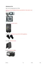
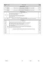
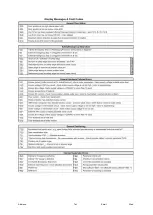
background image

Bolt Kit Contents

4x M20x

500mm

  Threaded bar (per gate)

8x M20 Bolts (per gate)

8x M20 Penny washers (per gate)

1x Resin fix tube

2x resin fix nozzles

4x M16x100

mm

 anchor bolts (for either catch post or center stop)
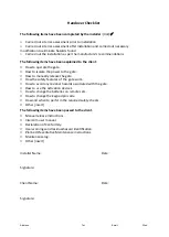
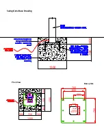
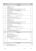
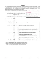
Swing Gate

 Bolt Down Procedure

1.

You need to prepare the ground to accept the 

swing gate

 tower. you should consult

 the

 issued CAD


drawings. Be sure to CAT scan any area before excavation

2.

The

re are 2 different ways the gates are installed depending on what you order. The gate is installed


i

2 steps if it is “cast-in”

 where the first pour is set below the ground level and the gate is bolted down


then a second pour is done up to the ground level. Please note! if the gate is being installed in an area


with a high water table you need to ensure you have adequate drainage. I

f you have opted for a “bolt-

down” installation


then 

it would just be 1 step where it is just bolted down to the plinth at ground level.

3.

the first pour


of concrete (mentioned above) this should be 700mm deep. When this has cured you


drill and chem fix


4

x M20 

threaded bars


into the surface to line up with the fixing holes in the gate


tower


base plate, (these have a nut above


and below the tower base


plate for adjustment/alignment


purposes).

4.

The gate leaf & tower will be 

lowered

 (base plate first) onto the threaded bar. here it will secured and


leveled up in all


direction

s

 ensuring that the tower sits up out of the hole to the correct (level) height.


This is a very


important step as when the


other gate is fitted. It will need to line up with the 

secondary


leaf

 or catch post depending on the order

. Please note that this is very important


as there is only a


MINIMAL adjustment once the gates


receive the second pour of concrete.

5.

Once

 the gate has now been 

lowered

 onto the threaded bar and has been leveled


accordingly


the


duct 

can be pushed through the hole in the gate tower

 if it is cast in

.

 If it is a bolt down then this would


be 

through the center of the base plate.

6.

Once the duct has been fed through the duct hole the second pour can be made

 (cast in only)

. You


must allow for ducting to link one tower to the other

 or to the catch post

 as you


have to have a


communication

s

 cable to allow the Master/Slave function

 and the photocells

.

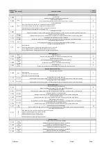
Summary of Contents for PF9700

Page 1: ...Opera on and Maintenance Manual Revision 10 0 2020 THIS DOCUMENT CONTAINS IMPORTANT INFORMATION IT MUST BE KEPT WITH THE GATE AT ALL TIMES...

Page 2: ...site direc on to which the gate was moving Emergency Stop Bu on located on the front of the gate tower this can be used before an incident happens Safe use warnings 1 Do not allow children people with...

Page 3: ...ly accelerate to full speed un l the intermediate limit is reached at which point the gate will decelerate for the remainder of the travel distance If a safety device is ac vated i e safety edge or ph...

Page 4: ...ually Only move the gate very slowly no faster than it moves in normal use Your installer will have demonstrated this at handover To return the gate to automa c opera on when the power is restored sim...

Page 5: ...gate the key switch will give a normal automatic open and close signal If you have two gates working in master and slave mode the key switch will only operate the gate that it is attached to Stop But...

Page 6: ...terfere with the gate and its safety sensors Keep the photo electric beam covers clean Safety checks These user safety checks should be conducted every few weeks by a responsible adult who has been sh...

Page 7: ...in a safe condition If the premises are also a workplace there are specific duties under regulation 5 and 18 of the Workplace Health and Safety and Welfare Regulations 1992 Failure to meet duties imp...

Page 8: ...otocells internal and external Sealing of photocell covers and cable entry Wire termina ons in control panel Sealing of control unit cover and cable entries Condi on of all wiring and junc on boxes Fu...

Page 9: ...ed safety checks Other insert The following items have been passed to the client Manual release instruc ons Intercom user manual Declara on of Conformity User warnings and residual hazard iden ca on P...

Page 10: ...nit PFL Swing Gate Drive 3 Phase PFL Drive 3 Phase 550Watts 60Nm Torque 58 RPM 2 3A Nominal Current 35mm Axle Photo beams Witt Argos T Argos R TX RX Through Beam Safe edge ASO 65mm profile Encoder Fei...

Page 11: ...ork done Company PPM Name Reac ve Signature Date Work done Company PPM Name Reac ve Signature Date Work done Company PPM Name Reac ve Signature Date Work done Company PPM Name Reac ve Signature Date W...

Page 12: ...nces Safety Household and similar electrical appliances Safety Electromagnetic compatibility EMC Part 6 1 Electromagnetic compatibility EMC Part 6 2 Electromagnetic compatibility EMC Part 6 3 Electrom...

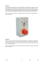
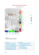
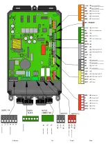
Page 13: ...Address Tel Email Web Engineers Sec on Not For End Users Control Panel Overview...

Page 14: ...Swing Gate Base Drawing Base plate Plan View 700 300 1300 700 1300 300 300 300 300 700 1300 700 700 224 224 CABLE ENTRY POSITION 600 300...

Page 15: ...u drill and chem fix 4x M20 threaded bars into the surface to line up with the fixing holes in the gate tower base plate these have a nut above and below the tower base plate for adjustment alignment...

Page 16: ...e the open limit switch is reached the count goes up by 1 2 With each full cycle the count goes up by 1 going open and closed 3 With every open command the count goes up by 1 P 981 0 to 3 2 0 Reset th...

Page 17: ...osition with auto close P 010 position adjustable with P 244 0205 Impulse command N O to fully open position without auto close close on next command 0501 Safety input N C safety reversing when closin...

Page 18: ...during opening continues to open 28 Safety during opening and closing after releasing during opening continues to open close after fully open 0 No close command 1 Close command only if triggered afte...

Page 19: ...ayed C 15 Housing tempreature displayed F 29 Display the address of slave module only on master 39 Display the cos phi power factor 40 Display the momentary DC Bus current in percent of maximum contin...

Page 20: ...Address Tel Email Web...

Page 21: ...Address Tel Email Web...

Page 22: ...Address Tel Email Web...

Page 23: ...Address Tel Email Web...

Page 24: ...Address Tel Email Web...

Page 25: ...Address Tel Email Web...

Page 26: ...Address Tel Email Web...

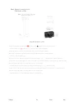
Page 27: ...Address Tel Email Web 24v From External PSU Switch to Drop Bolt...

Reviews: