
Address:
Tel:
Email:
Web:
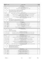
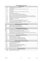
Parameter Function
Parameter
Display Adj. Range
Factory
Setting
Loop Detector Parameters
20 to 29
P.660
22
20: Deactivated
21: Evaluation only for command forwarding
22: Open command
23: Safety during closing with reversing
24: Safety during closing with stop
25: Verifies a suitably programmed external open command to act as safety check and also safety during closing
27: Safety during opening and closing, after releasing during opening continues to open
Loop detector channel 1
28: Safety during opening and closing, after releasing during opening continues to open, close after fully open
29: Gives leginimation for external open commends programmed accordingly
20: Deactivated
21: Evaluation only for command forwarding
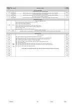
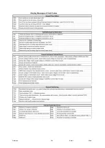
0 to 7
P.664
0
0: Without auto close time
1: With auto close time (P.010)
2: With auto close time (P.015)
3: Without auto close time, other auto close times blocked for other open commands
4: Auto close time as used before with last open command
5:Auto close time is stopped after activating in the open position and will go on after deactivation
6: With priority 1
Auto close time channel 1
7: With priority 2
0
0: Without auto close time
1: With auto close time (P.010)
2: With auto close time (P.015)
3: Without auto close time, other auto close times blocked for other open commands
4: Auto close time as used before with last open command
0
P.670
20 to 29
23
22: Open command
23: Safety during closing with reversing
24: Safety during closing with stop
25: Verifies a suitably programmed external open command to act as safety check and also safety during closing
27: Safety during opening and closing, after releasing during opening continues to open
28: Safety during opening and closing, after releasing during opening continues to open, close after fully open
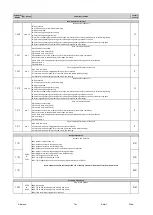
0: No close command
1: Close command only if triggered after open limit is reached
2: Close command after open limit is reached (command stored whilst opening)
3: Close command after safety released, also when opening
P.66C
0 to 3
Close command after detector channel 1
Loop detector channel 2
More options avaliable, check pages 196-197 of the Feig Parameter Description Total Overview manual
0
0: No close command
1: Close command only if triggered after open limit is reached
2: Close command after open limit is reached (command stored whilst opening)
3: Close command after safety released, also when opening
5:Auto close time is stopped after activating in the open position and will go on after deactivation
6: With priority 1
7: With priority 2
P.67C
0 to 3
Close command after detector channel 2
29: Gives leginimation for external open commends programmed accordingly
P.674
0 to 7
Auto close time channel 2
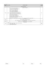
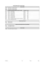
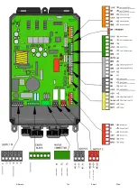
0000: Deactivated
0101: TST SURA1 safety edge card fitted (1 8k2 input)
0106: TST SURA6 safety edge card fitted (6 8k2 inputs)
0302: Loop card fitted (single or dual channel)
P.802
0000
to
0302
0302
Plug in card options
Output 1 and 2 profiles
0001: Output is perminently on
0101: Output activates in the open position
0201: Output activates in the closed position
0401: Output active whilst there are no faults showing on the controller
0801: Output is active during opening and closing operations
1101: Maglock receives voltage when in the closed position
1201: Traffic light on the inside of site
1210: Traffic light on the outside of site
12A1: Traffic light without direction, Flashing during close delay timer (P.025)
Accessory Parameters
Output Parameters
0000
to
3201
P.701
P.702
P.70F
0101
0201
0801
Summary of Contents for PF9700
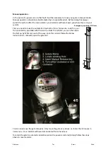
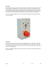
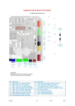
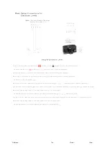
Page 13: ...Address Tel Email Web Engineers Sec on Not For End Users Control Panel Overview...
Page 20: ...Address Tel Email Web...
Page 21: ...Address Tel Email Web...
Page 22: ...Address Tel Email Web...
Page 23: ...Address Tel Email Web...
Page 24: ...Address Tel Email Web...
Page 25: ...Address Tel Email Web...
Page 26: ...Address Tel Email Web...
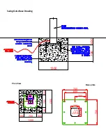
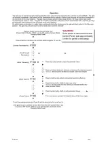
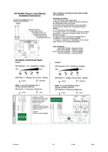
Page 27: ...Address Tel Email Web 24v From External PSU Switch to Drop Bolt...


