background image

Please read these instructions completely before use


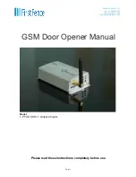
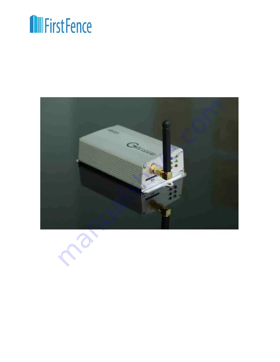
GSM Door Opener Manual

Model:

1.

: 1 Output 2 Inputs

PFGOGSM

Page 1

Phone: 01283 512 111 

Fax:  01283 480 522 

Web: firstfence.co.uk 

Mail: sales@firstfence.co.uk

Summary of Contents for PFGOGSM

Page 1: ...lease read these instructions completely before use GSM Door Opener Manual Model 1 1 Output 2 Inputs PFGOGSM Page 1 Phone 01283 512 111 Fax 01283 480 522 Web firstfence co uk Mail sales firstfence co uk ...

Page 2: ...onnection 5 5 3 Wiring Diagram 5 5 4 Power Supply 6 6 LED INDICATORS 7 7 OPERATION 8 8 PROGRAMMING 8 8 1 Programming by dial ing in 8 8 2 Programming by text message 9 9 ADMINISTRATOR NUMBER 10 10 CHECK SIGNAL STRENGTH 10 11 CHECK RELAY STATUS 10 12 HOW TO RESET THE UNIT WHEN YOU FORGET THE PASSWORD 10 13 USER COMMANDS 11 14 SERIAL MODELS 13 15 SPECIFICATIONS 13 Page 2 ...

Page 3: ...ough theVentilation slots 7 Avoid using the equipment during an electrical storm There is a remote risk of electrical shock from lighting 2 BRIEF INTRODUCITON GSM door opener is a GSM switch remote control system which can activate automatic gates with a free call from you mobile phone The users phone numbers are programmed into the device by SMS or call The device recognizes incoming Caller ID an...

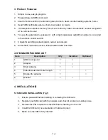
Page 4: ...tion 7 2 inputsfor switchingcontacts alarm output sensors etc 8 Automation industrial process intruder alarm dialer and more 4 STANDARDPACKING LIST Item Description Q ty Included Optional 1 GSM door opener 1 2 Adapter 1 3 Short Antenna 1 4 External Antenna 3 meter length 1 5 Bracket for antenna 1 6 Manual 1 4 INSTALLATION 5 1 SIM CARD INSTALLATION F ig1 1 Ensure power i soff before instering or re...

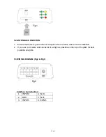
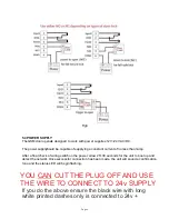
Page 5: ...t the location where it wil be installled 2 If you use a 3 meters antenna install it as hi gh as possible on the top of the pillar for best possilbe reception 5 3 WIR ING DIGRAM Fig2 Fig3 Interface instroduction 1 INPUT2 4 NO1 2 GND 5 NC1 3 INPUT1 6 COM1 Fig1 Fig2 Page 5 ...

Page 6: ...al check of wiring switchon the power allow 20 30 seconds for the unit to boot up and detect the network Oncesuccessful connection has been made the unit will sound a confirmation tone and the status LED will begin flashing YOU CAN CUT THE PLUG OFF AND USE THE WIRE TO CONNECT TO 24v SUPPLY If you do the above ensure the black wire with long white printed dashes only is connected to 24v Page 6 ...

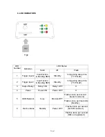
Page 7: ...nput 1 Input1 active Sending SMS Standby In triggering setup time 15 Time 3 Output Relay 1 Relay1 ON Relay1 OFF X 4 Power Power ON Power OFF X 5 GSMNetwork busy Module OFF Flashes once per second Search network Flashes once per 3seconds Standby 6 Device status Standby Power OFF Flashes once per second No SIM inserted Flashes twice per second SIM not registered Page 7 ...

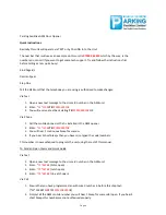
Page 8: ... back stating 7407595062810 OK Via Phone 1 Call the mobile phone sim that is installed in the GSM opener 2 Enter 12 1234 7407595062810 3 You will hear 1 continuous bleep for success 4 If you hear 3 short bleeps then you have miss typed the code numbers This number is now authorised to program the unit using the rest of this manual To Send an Open Command Quick Guide Via Text 1 Open a new text mess...

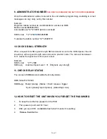
Page 9: ...71 5678 To latch or hold door by pressing 72 5678 To unlatch door by pressing 73 5678 Above operation same as sending SMS commands This is for door open option for telephone numbers not stored 8 Programming Programming can be carried out either by text message or by dailing into the GSM door opener 8 1 Progrmming by dialing in Dial the SIM card telephone number The unit will answer the call and yo...

Page 10: ...command Code2 command Code3 3 Each SMS must start with the pass code default 1234 in the following format 12 1234 Followedimmediately by a command Program with the following format 12 1234 71 country code 721 phonenumber 721 phonenumber 721 phonenumber Country code 1 3 digits for Ireland insert 353 UK insert 44 USA insert 1 Do not using any leading zeros The passcode 12 1234 only needs to be put a...

Page 11: ...ith a signal strength code and service provider name The code will be between 0 31 means the signal level is from poor to best Example SMS format 21 1234 SMS reply Vodafone Signal Level 31 Signal is very strong 11 CHECK RELAY STATUS You can send SMS command code to check relay status SMS format 24 1234 SMSReply Relay 1 status Status Hold release trigger Input 1 status Input 2 status status high lo...

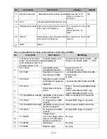
Page 12: ...nding SMS duration when input 1 continuestriggering Time 0 60 minutes 0 min nodelay 8 17 Time Sending SMS duration when input 2 continues triggering Time 0 60 minutes 0 min nodelay 9 18 Status SetInput1 status Status 0 or 1 0 N O 1 N C 0 10 19 Status SetInput2 status Status 0 or 1 0 N O 1 N C 0 11 20 mode SetInput1 mode Mode 0 or 1 0 Egress 1 Trigger 1 12 21 mode SetInput2 mode Mode 0 or 1 0 Egres...

Page 13: ...signal strengthand operator Signal Level 0 31 From poor to strong 3 22 1234 Replylist of ringing in to open phone number s number 1 number2 number3 E Next page N End 4 23 1234 Replylist of alarm contact numberswheninputsare triggered number 1 number2 number3 5 24 1234 Checkrelayandinputs status Relay 1 status status h old release trigger Input1 status status high low Input 2 status status high low...

Page 14: ...m 250mA typically 55mA GSM Module Cinterion Germany GSM Frequency GSM 850 900 1800 1900 or GSM 900 1800 MHz Power Consumption Standby 42mA hr Relay on 83mA hr Physical size 9 5 L X 6 0 W x 2 5 H cm Antenna Short Antenna Humidity Less than 80 RH Operating Temperature 20 to 50 Page 14 Thank you for purchasing our products GSM Door Opener ...

Reviews: