background image


14


Adjustments

H

Operation 

(Continued)

• Save all instructions 

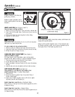
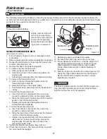
WHEEL LOCK PINS

 (See Figures 2 and 11)

Place wheels in tilling position.

1.  Remove lock pin. Align hole in axle with hole in wheel hub.

2.  Insert lock pin through holes, fold lock pin ring to secure  

  pin to axle.

3.  Firmly lock wheel and axle together before tilling.

4.  Repeat for other wheel.

WARNING

Always have both wheel lock pins in or out. Do not operate 

tiller with only one wheel locked.

To place wheels in free-wheel position.

1.  Remove lock pin. Slide wheel inward toward machine.

2.  Insert pin in axle only, fold lock pin ring to secure pin to axle.

3.  Wheel should turn freely on axle.

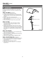
HANDLEBAR HEIGHT ADJUSTMENT 

(See Figure 4)

Adjust handlebar height.

The ideal height of the handlebar varies with operator 

height and the depth of tilling. To adjust handlebar height:

1.  Unscrew nuts and remove top bolts on each side.

2.  Loosen the lower bolts. Do not remove.

3.  Align handlebar to desired holes on the lower handlebar  

 mount.

4.  Install bolts and nuts. Retighten all four bolts securely. 

DEPTH REGULATOR LEVER 

(See Figure 3)

Tilling depth is controlled by the height of the

depth regulator lever. To adjust tilling depth:

1.  Remove pin.

2.  Raise the depth regulator lever to position tines at    

  chosen tilling depth.

3.  Align hole in depth regulator lever with hole in depth   

  regulator bracket and replace pin.

Depth Regulator Lever Down

 = Shallower tilling.

Place the pin in the top hole of the depth regulator lever for 

shallowest tilling.

Depth Regulator Lever Up

 = Deeper tilling.

Place the pin in the bottom hole of the depth regulator lever 

for deepest tilling.

WARNING

Engine should be off before ad-

justing any controls.

Extreme caution should be used 

when operating tiller in the reverse 

direction. 

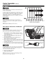
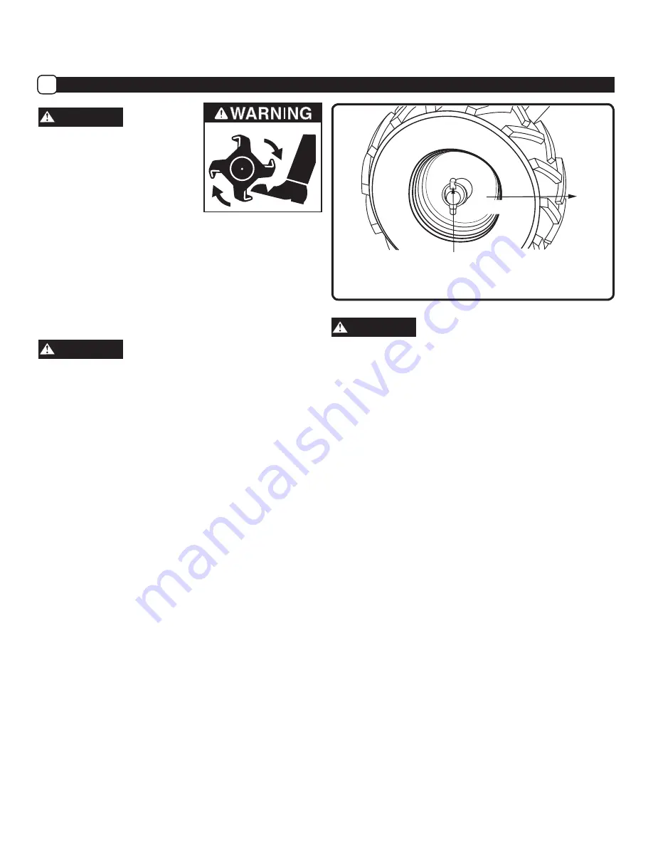
Wheel lock pin in free-wheel position

(axle holes only)

FRONT

Figure 11

WARNING

Do not adjust tilling depth unless drive safety control levers are 

released to neutral position.

Always set the depth regulator lever in the transport posi-

tion before starting engine, that is, place the detent pin in 

the highest hole of the depth regulator lever. 

Summary of Contents for PRTT-460

Page 1: ...6 9 7 y l b m e s s A Engine Preparation 10 5 1 1 1 n o i t a r e p O 9 1 6 1 e c n a n e t n i a M Technical Service 19 Troubleshooting 20 4 2 1 2 y t n a r r a W 5 2 s i a n a r F 6 2 l o a p s E 1...

Page 2: ...and deadly gas NEVER run unit indoors or in a poorly ventilated area Do not use if children or bystanders are present Do NOT touch hot muffler or cylinder These parts are extremely hot from operation...

Page 3: ...and in this manual Be thoroughly familiar with the controls and the proper use of the tiller before starting Know how to stop the engine quickly Familiarize yourself with all the safety and operating...

Page 4: ...are in the locked position This acts as a brake for the tiller Always start the tiller on the level surface WARNING Disengage clutch lever and stop engine before leaving the tiller in operating positi...

Page 5: ...facturer Keep the tiller in safe working condition Check all fasteners at frequent intervals for proper tightness When servicing or repairing the tiller do not tip the machine over or up unless specif...

Page 6: ...ter 7 Recoil Starter Handle 8 Spark Plug Spark Plug Wire 9 Depth Regulator 10 Throttle Control 11 Fuel ON OFF Valve 12 Choke Control 13 On Off Switch 14 Fuel Tank Cap 15 Oil Dipstick 16 Forward Lever...

Page 7: ...questions regarding their meaning or how to comply with these instructions reread the complete safety instruction text on the preceding pages or contact your lo cal dealer Should any of the safety lab...

Page 8: ...taining the following a Combination wrenches b 4 M8x25mm bolts flat washers lock nuts for assembling front carry handle 1 Remove all parts and packaging components 2 Use a utility knife to cut all 4 v...

Page 9: ...he tine blade The sharp cutting edge should be facing the direction of tine rotation for your tiller 2 Install the tine assemblies on each tine axle Secure with M10x50mm bolts and lock nuts Do not ove...

Page 10: ...See Figure 5 1 Slide the upper handle down over the lower handle and align the holes 2 Insert the saddle bolts into the holes as shown and securely with the handle knobs 3 Tighten the handle knobs sec...

Page 11: ...ver is set so the main frame of the tiller is level See Figure 6 2 Remove the oil fill cap dipstick and wipe clean with cloth See Figure 6 3 Insert dipstick into fill spout but do NOT screw in Remove...

Page 12: ...ine is hot or running Always move outdoors to fill tank Wheels must always be locked in the tilling position when engine is running Do not operate the tiller with the wheel lockouts unlocked Always se...

Page 13: ...handlebars You can stop the tiller by releasing the drive safety control levers to the neutral position CAUTION Always press the forward or reverse drive levers down completely onto the handle bar gri...

Page 14: ...Please read this section and all operating and safety instructions before starting your tiller As a safety precaution the drive safety control levers will not lock in the forward or reverse position...

Page 15: ...holes on the lower handlebar mount 4 Install bolts and nuts Retighten all four bolts securely DEPTH REGULATOR LEVER See Figure 3 Tilling depth is controlled by the height of the depth regulator lever...

Page 16: ...w instructions under Tilling section This will allow for shallow tilling With the drag stake in this position make several light passes over the area to be tilled Reset for deeper depths with successi...

Page 17: ...il every 25 hours if operating under heavy load or in high temperatures 4 Clean air filter every 10 hours if operating under dusty conditions WARNING Use only GENUINE replacement parts Other parts may...

Page 18: ...t from underneath the unit and up around the reverse belt idler b Place the lower loop of the belt around the forward portion of the transmission pulley c Replace the reverse belt idler into the rever...

Page 19: ...Do not overfill Check the oil level annually To check the oil level 1 Move tiller to level ground 2 Remove oil level dipstick located between the handlebar mounts on the engine mount If the oil level...

Page 20: ...out of gasoline 2 Change the oil by following instructions under How to Change the Oil 3 Remove the spark plug from the cylinder Pour one ounce of oil into the cylinder Slowly pull the recoil start g...

Page 21: ...el tank Fill with fresh fuel 6 Take unit to an authorized service center for Carburetor adjustment Excessive vibration noise 1 Loose parts 2 Engine problems above 3 Abnormal noise or squeal coming fro...

Page 22: ...ly if so equipped muffler gasket ex haust manifold Crankcase Breather Assembly Breather connection tube Miscellaneous Parts Used in Above Systems Hoses belts connectors and assemblies Evaporative Emis...

Reviews: