background image


9

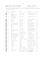
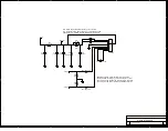
Zener Mod: 

Omit R17, R20, R23 & R26. Sub the following: 

R18,R21,R24,R27 

10V zener 2% 

78-BZX85B10-TAP 

0.10 

R19,R22,R25,R28 

100 ohm Pot  

72-T93YB-100 

1.58 

Notes:    

- C14 & C15 are input coupling capacitor footprints that are PCB 
jumpered. These can be cut open and used if DC blocking is needed.  
- R36 & R37 can be cut open and used with low value power resistors 
if you have high filament voltage.  
- R32 & C13 omitted. 

Go to 

www.mouser.com

 and log in to your account. Use Service & Tools > Parts 

List Importer. Paste list into window and Import to My Current Order. CRTL-C 
to copy. CTRL-V to paste. 

/* start cut-n-paste */ 
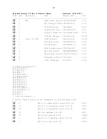
71-RN60D-F-47.5K 2 
71-RN60D-F-475K 6 
71-RN60D-F-1.0K 6 
594-5083NW300K0J 2 
281-27K-RC 2 
281-33K-RC 2 
594-5083NW470R0J 4 
72-T93YB-10K 4 
594-5083NW360K0J 1 
72-T93YB-100K 2 
594-5083NW6K800J 1 
594-5083NW100R0J 4 
71-RN60D-F-150K 2 
527-CL90 1 
71-RN55D-F-10 4 
71-RN55D-F-1.0K 4 
71-RN55D-F-100 4 

75-715P400V0.1 4 
647-UVR1V471MPD 4 
5985-380-450V121 4 
140-500N5-270J-RC 2 
140-500N5-330J-RC 2 
140-500N5-180J-RC 2 
5989-250V.22-F 2 

UF4007-E3/54 2 

571-114376644 1 
571-14376645 4 

571-282837-2 

78-BZX85B10-TAP 4 
72-T93YB-100 4 
/* end cut-n-paste */ 

Summary of Contents for Tube st35

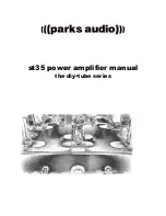
Page 1: ...st35 power amplifier manual the diy tube series ...

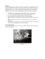
Page 2: ...00VDC are present in this project Use a Variac or isolation transformer while working on and testing the unit Use a rubber mat to stand on while working on and testing the unit Keep one hand in your back pocket if probing voltages with a DMM Wrap a small piece of electrical tape around the test lead probe shaft to expose just the tip Do not connect or disconnect wires to the terminal blocks when u...

Page 3: ...A Using the Assembly Drawing The assembly drawing is a quick reference to what component is where and the numbering scheme for the connectors It is also a good place to make any notes Soldering This PCB is a double sided plated through hole design on 094 FR4 material with LPI liquid photo imagable solder mask and 2 ounce copper per side When soldering these components let the solder flow through t...

Page 4: ...lder the connectors as solder could then spill under the connector causing a short 9 Stuff R42 the IRCL making sure it doesn t lean on or touch the J1 terminal block as it gets warm 10 Stuff the 4 filter capacitors Mind the polarity If these are substituted the diameter must be 25mm or less The height must be 30mm or less to fit in a 2 high chassis 11 Carefully go over your work looking for a any ...

Page 5: ... a real low impedance 2 Probe your DMM from J4 pin 3 right channel to ground and adjust R30 until the resistance is 20 3K set to 28 3K if using the 16 ohm tap as feedback as in the original Z565 3 Probe your DMM from J3 pin 3 left channel to ground and adjust R31 until the resistance is 20 3K set to 28 3K if using the 16 ohm tap as feedback as in the original Z565 4 Your feedback is set Adjusting ...

Page 6: ...the outside test point Adjust R19 until the voltage is 350V or 350mV 8 Probe your DMM set to DC volts from the test point which is sandwiched between the R25 R28 to ground V5 is adjusted with the inside test point Adjust R28 until the voltage is 350V or 350mV 9 Probe your DMM set to DC volts from the test point which is sandwiched between the R25 R28 to ground V6 is adjusted with the outside test ...

Page 7: ...n J2 J3 J4 and J5 for triode operation Do not attach any UL taps to pin 2 on these connector blocks if you do this Do not populate C20 C21 If you are using a filament supply with a center tap and choose to use the center tap do not populate R40 and 41 These are for non CT filament supplies such as the Dynaco PA 774 SW2 can be omitted and the secondary CT wired straight to ground if a standby switc...

Page 8: ...72 T93YB 10K 1 58 1 R29 360k 2W 594 5083NW360K0J 0 10 2 R30 R31 100K Pot 72 T93YB 100K 1 33 1 R33 6 8k 2W 594 5083NW6K800J 0 10 4 R34 R35 R40 R41 100 2W 594 5083NW100R0J 0 10 2 R38 R39 150k 1 2W 71 RN60D F 150K 0 11 1 R42 Inrush Limiter 527 CL90 2 21 4 R43 R44 R45 R46 10 Ohm 1 4W 71 RN55D F 10 0 10 4 R47 R48 R49 R50 1k 1 4W 71 RN55D F 1 0K 0 11 4 R51 R52 R53 R54 100 1 4W 71 RN55D F 100 0 11 4 C1 C...

Page 9: ... Tools Parts List Importer Paste list into window and Import to My Current Order CRTL C to copy CTRL V to paste start cut n paste 71 RN60D F 47 5K 2 71 RN60D F 475K 6 71 RN60D F 1 0K 6 594 5083NW300K0J 2 281 27K RC 2 281 33K RC 2 594 5083NW470R0J 4 72 T93YB 10K 4 594 5083NW360K0J 1 72 T93YB 100K 2 594 5083NW6K800J 1 594 5083NW100R0J 4 71 RN60D F 150K 2 527 CL90 1 71 RN55D F 10 4 71 RN55D F 1 0K 4 ...

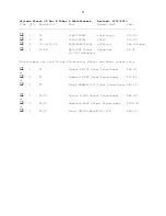
Page 10: ...nding post 164 19B2 EX 3 95 4 Red Test Points 530 105 0802 1 0 72 2 Black Test Points 530 105 0803 1 0 72 6 Standoffs 1 4X1 2 534 2210 0 33 6 625 Bushings 836 2073 0 16 start cut n paste 112 R13 66B G 1 161 R3014 E 1 504 GMA 2 1 545 P004 006 1 313 2420F 100K 1 546 1444 29 1 546 1434 29 1 568 NYS367 9 1 568 NYS367 2 1 164 19B2 EX 2 530 105 0802 1 4 530 105 0803 1 2 534 2210 6 836 2073 6 end cut n p...

Page 11: ...4 V5 V6 6BQ5 EL84 6p14p el84jjmq 44 99 quad 6 V1 V6 9pin PCB Socket 9pinpccer 2 35 0 750 diameter Transformers are from Triode Electronics Mouser and Edcor respectively 1 T1 Dynaco PA 774 Power Transformer 64 95 or 1 T1 Hammond 270HX Power Transformer 87 62 or 1 T1 Edcor XPWR005 120 Power Transformer 43 21 2 T2 T3 Dynaco Z 565 Output Transformer 84 95 or 2 T2 T3 Hammond 1650F Output Transformer 10...

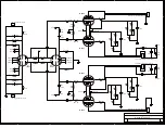
Page 12: ...R43 10 R44 10 R9 27K R15 475K R45 10 R16 475K R8 300K J2 Output Transformer Hookup 1 2 3 C3 0 1uF J3 Output Transformer Hookup 1 2 3 R46 10 J4 Output Transformer Hookup 1 2 3 J5 Output Transformer Hookup 1 2 3 R53 100 R51 100 R48 1K R27 1K R31 100k 1 3 2 R49 1K V2 12AU7 h 5 g 2 g 7 a 6 h 4 hT 9 k 3 a 1 k 8 C17 27pF R2 47 5K C16 27pF C8 470uF R23 470 J6 Right Channel Input 1 2 C22 0 22uF C23 0 22uF...

Page 13: ...heir trace jumpers and use two low value resistors like using one or two 0 1 ohm power resistors 72 RWM410 R1 5 R34 R35 can be subbed with a two pole connector 571 14376644 and a small choke 1 or 1 5H and around 50 ohms DCR e g a Hammond 546 158SA or Triad C 24X D1 UF4007 D2 UF4007 R33 6 8K 2W R34 100 2W R36 jumpered R37 jumpered C10 120uF C9 120uF R35 100 2W C11 120uF C12 120uF R41 100 R40 100 J1...

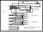
Page 14: ...primary winding green white black diytube Stereo 35 PCB Rev E Connect directly to chassis PRIMARY Blue to Red 170 ohms Green to Red 43 ohms Green White to Red 50 ohms Blue White to Red 196 ohms SECONDARY Yellow to Black 1 ohm Orange to Black 7 ohm Z 565 Left Output Transformer Logical Layout of the diytube Stereo 35 with DynacoTransformers J7 1 2 J2 1 2 3 Left Channel J3 1 2 3 J4 1 2 3 J5 1 2 3 J1...

Page 15: ...white black diytube Stereo 35 PCB Rev E Connect directly to chassis Edcor CXPP25 MS 8K 23 Left Output Transformer Logical Layout of the diytube Stereo 35 with Edcor Transformers orange red blue blue white white brown brown green yellow white orange Edcor CXPP25 MS 8K 23 Left Output Transformer 4 OHM 1 Right Channel J2 1 2 3 F1 J1 1 2 3 4 5 6 7 8 9 10 SW1 J3 1 2 3 GND 1 Left Channel 8 OHM 1 J4 1 2 ...

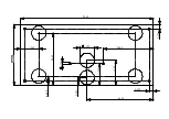
Page 16: ...9 250 4 250 1 000 0 156 0 640 3 650 1 500 0 300 0 300 0 550 1 750 4 625 3 480 1 260 ...

Reviews: