exceed the specified value in exceptional
circumstances.
7. Before starting the equipment
Important!
Before you connect the equipment to the
mains supply make sure that the data on the
rating plate are identical to the mains data.
Always pull the power plug before making
adjustments to the equipment.
Check the drilling point for concealed electrical
cables, gas and water pipes using a cable/pipe
detector.
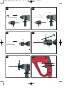
7.1 Additional handle (Fig. 2 – Item 3)
For safety reasons you must only use the
hammer drill with the additional handle.
The additional handle (3) enables you to
achieve better stability whilst using the
equipment. Do not use the equipment without
the additional handle (3). The additional handle
(3) is secured to the equipment by a clamp.
Turning the additional handle (3) clockwise
tightens this clamp. Turning it anti-clockwise will
release the clamp.
The supplied additional handle (3) must first
be fitted. To do this, turn the additional
handle (3) until the clamp is opened wide
enough for you to slide the additional handle
onto the equipment.
After you have mounted the additional
handle (3), swivel it to the most comfortable
working position for yourself.
Now turn the additional handle (3) in the
opposite direction again until the additional
handle (3) is secure.
The additional handle (3) is suitable for both
left-handed and right-handed users.
7.2 Depth stop (Fig. 3 – Item 13)
The depth stop (13) is held in place by
clamping with the lock (4) on the additional
handle (3).
When mounting the depth stop (13), make sure
that the catch is on the bottom side.
Press the lock (4) and keep it pressed it
while you adjust the depth stop (13).
Set the depth stop (13) to the same level as
the drill bit.
Pull the depth stop (13) back by the
required drilling depth.
Let go of the lock (4).
Now drill the hole until the depth stop (13)
touches the workpiece.
7.3. Tool insertion (Fig. 4)
Clean the tool before insertion and apply a
thin coating of drill bit grease to the shaft of
the tool.
Pull back and hold the locking sleeve (2).
Turn and push the dust-free tool into the tool
mounting as far as it will go. The tool will
lock automatically, after the locking sleeve
is released.
Check that it is properly secure by pulling
the tool.
7.4. Tool removal (Fig. 5)
Pull back and hold the locking sleeve (2) and
remove the tool.
7.5 Dust collection device (Fig. 8)
Slide the dust collection device (16) over the
drill bit before carrying out any hammer drilling
vertically above your head.
7.6. Fitting the additional scroll chuck
(Fig. 4)
Clean the scroll chuck (14) before fitting it
and apply a thin coating of drill bit grease to
the scroll chuck shaft.
Pull back and hold the locking sleeve (2).
Turn and push the dust-free scroll chuck
(14) into the tool mounting as far as it will
go. The scroll chuck (14) will lock
automatically after the locking sleeve is
released.
Check that it is secure by pulling the scroll
GB/IE/
CY
12
Anleitung_BMH_1100_4258398:_ 21.11.2008 7:40 Uhr Seite 12
Summary of Contents for BMH 1100
Page 1: ...Anleitung_BMH_1100_4258398 _ 21 11 2008 7 39 Uhr Seite 1 ...
Page 2: ...18 30 42 54 67 Anleitung_BMH_1100_4258398 _ 21 11 2008 7 39 Uhr Seite 2 ...
Page 5: ...5 10 A 5 C E D B Anleitung_BMH_1100_4258398 _ 21 11 2008 7 40 Uhr Seite 5 ...
Page 80: ...80 Anleitung_BMH_1100_4258398 _ 21 11 2008 7 41 Uhr Seite 80 ...
Page 81: ...81 Anleitung_BMH_1100_4258398 _ 21 11 2008 7 41 Uhr Seite 81 ...
Page 82: ...Anleitung_BMH_1100_4258398 _ 21 11 2008 7 41 Uhr Seite 82 ...


