13
NI
IE
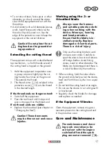
Ensure that the bottom shaft tube is
sitting irmly and safely before start
-
ing the equipment.
4.
Dismantling:
Release the handle-fastening screw
(11). Push the safety lever (32) and
pull the two shaft tubes apart.
Mounting the multi-
functional handlebar
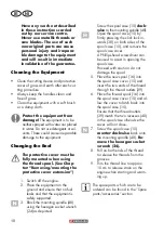
1. Place the large spring (55) between
the intake on the upper shaft tube (35)
and the lower section of the handlebar
bracket (34).
2. Place the multi-functional handlebar
(10) and the small spring (56) into the
handlebar bracket (34).
3. Fasten the multi-functional handlebar (10)
to the upper section of the handlebar
bracket (34) and star-shaped knob (33).
Tighten the star-shaped knob (33) by hand.
Initial Operation
Warning! Before initial opera-
tion of the equipment, it must
be checked that the condition
is safe for operation. If there
is any doubt, do not start the
equipment.
Observe the following points in par-
ticular:
• Check the cutting tools for damage and
wear.
• Correct installation of the cutting head
• Easy movement of all switches
• Secure sit of the spark plug connector. If the
connector is loose, sparks can be formed
and thus ignite any leaking fuel-air mix.
• Ensure the handles are clean in order to be
able to guide the equipment safely.
serious injury. You can avoid
kickbacks through caution
and proper technique.
While working with the 3- or 4-tooth bla-
de there is a risk of kickback if the blade
edge hits an obstacle (stone, wood).
• Hold the device with both hands.
• Make sure there are no obstacles on the
ground and do not use the 3- or 4-tooth
blade near fences, metal posts or similar.
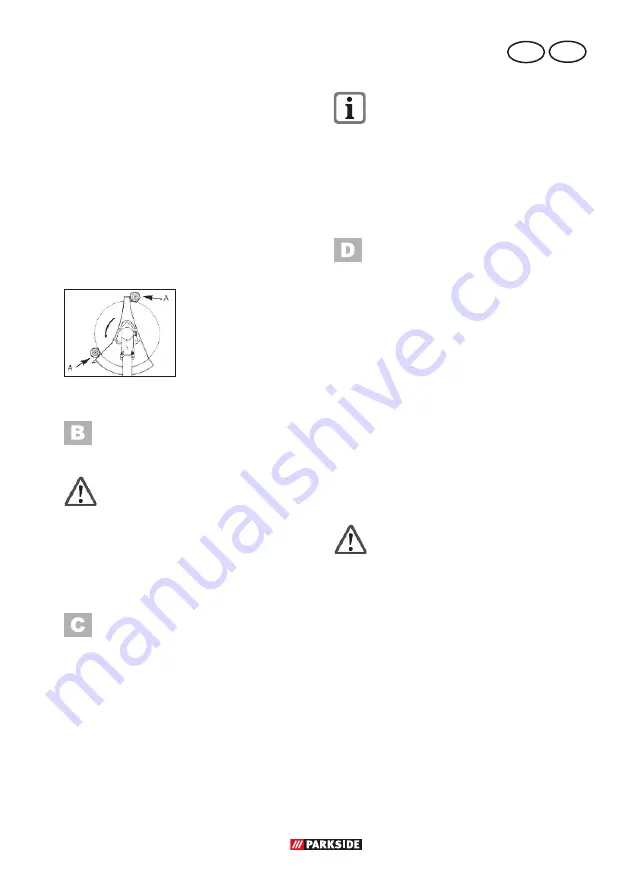
Use only properly
sharpened tools. To cut
thick stems, switch the
device to position A.
Assembly
Installing the protective
cover
Never use the device without
the protective cover correctly
installed! Risk of injury.
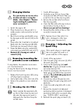
1. Position the protective cover on the shaft
holder (31).
2. Attach the protective cover using the hinge
and screws (30).
Fitting the Two-Part Tube
1. Loosen the tube ixing screw (11) on
the top shaft tube (8).
3. Push the safety lever (32) and insert
the two shaft tubes into one another.
Release the safety lever (32). The safety
lever (32) of the upper shaft tube (8)
must latch into the hole provided on the
lower shaft tube (12).
3. Retighten the tube ixing screws (11) by
hand.
Summary of Contents for PBS 2 A1
Page 51: ...51...
Page 52: ...52...
Page 57: ...J 41 44 2 6 36 45 7 14 13 46 16 47 43 42 M...
Page 58: ...48 49 29 28 49 50 50 15 51 51 24 53 57 24 53 54 52 24 58 9 8 20 cm...
Page 59: ......


