GB
│
IE
│
NI
│
9
■
PDFS 1300 A1
Assembly
Fitting/changing the cutting disc
WARNING! RISK OF INJURY!
■
Switch the appliance off and remove the
power plug before starting any work on the
appliance .
NOTE
■
Only use diamond cutting discs with diame-
ters corresponding to the inscriptions on the
appliance .
♦
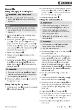
Set the cutting depth (using the locking screw
) to the minimum position .
♦
Actuate the spindle lock and turn the clamping
screw until the spindle lock clicks into
place . Loosen the clamping screw / washer
with the hex key . Now remove the clamping
screw / washer and the clamping flange
(see also fold-out page, fig . A) .
♦
Remove the cutting disc .
♦
Fitting a cutting disc is carried out in the
reverse order .
♦
Actuate the spindle lock and turn the clamping
screw until the spindle lock clicks into
place . Use the hex key to firmly tighten the
clamping screw .
WARNING!
►
The arrow on the cutting disc must match
the direction of rotation arrow (running direc-
tion, marked on the appliance) .
■
Make sure that the cutting disc is suitable for
the speed of the tool .
Fitting/setting the rip fence
♦
Undo the wing screw and insert the rip fence
into the rip fence slot .
♦
Set the desired cutting width using the scale on
the rip fence and the rip fence slot . The
rip fence slot serves as an orientation mark
(see also fold-out page, fig . E) .
♦
Retighten the wing screw .
Fitting the water inlet hose
WARNING!
►
Check the correct function of the residual
current circuit breaker before each use!
►
Work with the appliance in a horizontal
position and not overhead to prevent water
from entering the machine .
►
Before each use, check the water supply
system for leaks .
CAUTION!
►
Do not connect the appliance to a water
supply system with more than 6 bar!
►
Only use water as coolant .
♦
Set the cutting depth (using the locking screw )
to the minimum position .
♦
Using a Phillips screwdriver and the accessory
screw supplied , fit the water inlet to the
housing (see also fold-out page, fig . B) . Please
note that the water inlet must be guided
around the cutting depth adjustment . The two
water outlets of the water inlet must be locat-
ed on the side of the cutting disc (see also
fold-out page, fig . F) .
♦
Push the water inlet hose into the water
inlet .
♦
Insert the other end of the water inlet hose
into the water connection adapter .
♦
Connect the water connection adapter to a
water hose with a suitable diameter of approx .
19 mm . Check for a tight fit by pulling on the
water hose .
♦
Open the valve on the water inlet .
♦
Carefully adjust the amount of water at the water
source so that there is always enough water on
the cutting disc and the cutting area .
♦
Disconnect the water supply after completion
of the work .
Summary of Contents for PDFS 1300 A1
Page 3: ...A B C ...
Page 4: ...E D F ...

