■
10
│
GB
│
IE
│
NI
PDFS 1300 A1
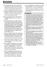
Installing the dust extraction system
On delivery, the connection point of the adapter
for dust extraction is closed off . To install the
dust extractor, proceed as follows:
♦
Remove the screws from the housing and
remove the protective cover .
♦
Using the screws provided, fasten the adapter
for dust extraction onto the dust outlet .
♦
Connect an approved dust and chip extraction
device .
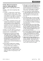
Operation
WARNING!
►
Prevent dripping water from dripping along
the power cord into the power outlet or plug .
To do this, form a loop from the mains cable
underneath the mains socket . This prevents
any dripping water from getting into the
mains socket .
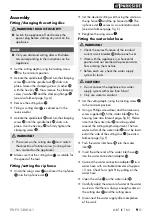
Residual current circuit breaker
WARNING!
►
Check the correct function of the residual
current circuit breaker before each use !
♦
Connect the residual current circuit breaker
to the power grid .
♦
Press the reset button until the indicator
is red .
♦
Press the Test button until the indicator is
black . This shows that the test was successful .
If the indicator continues to indicate red, the
residual current circuit breaker is defective
and must be repaired by qualified personnel!
WARNING!
►
Do not operate a appliance with faulty circuit
breakers!
♦
After a successful test, press the reset button
again to switch the appliance back on .
Switching on and off
WARNING!
►
To avoid the risk of electric shock, make sure
that no water gets into the appliance . Do not
touch the power plug with wet hands .
CAUTION!
►
Wait until the appliance has reached the
maximum speed and use a low feed rate to
achieve clean cuts .
Switching on:
♦
Press the ON/OFF switch .
Switching off:
♦
Release the ON/OFF switch .
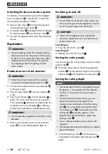
Setting the cutting angle
You can change the cutting angle using the cutting
angle scale .
■
Undo the wing screw of the cutting angle pre-
selector . Set the desired angle on the cutting
angle scale and retighten the wing screw .
Setting the cutting depth
NOTE
►
We recommend that the cutting depth should
be approx . 3 mm greater than the material
thickness . This ensures that you achieve a
clean cut .
►
To determine the correct setting, you can
place the machine on the edge of the
material to be machined so that the cutting
disc can swing freely downwards when
the locking screw is loosened . Once the
cutting disc protrudes approx . 3 mm
beyond the material thickness, tighten the
locking screw .
►
Use a similar procedure if you want to mill
a groove .
►
We recommend testing the setting on a sample
piece of material .
♦
Undo the locking screw . Set the desired
cutting depth and tighten the locking screw
again .
Summary of Contents for PDFS 1300 A1
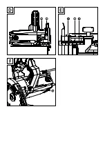
Page 3: ...A B C ...
Page 4: ...E D F ...

