11
GB/IE/NI/CY/MT
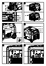
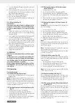
12.2 Check the oil level (Fig. 4 + 5)
1. Place the power generator/inverter on a level, even surface.
2. Remove the ignition key (B) from the ignition lock (14).
3. Remove the cover (4) as described in 9.3 (Fig. 4).
4. Unscrew the oil dipstick (19).
5. Wipe the oil dipstick (19) with a clean, lint-free cloth.
6. Screw the oil dipstick (19) back into the filler neck until it
reaches the stop.
7. Pull the oil dipstick (19) out and read the oil level in the
horizontal position. The oil level must be between L (low)
and H (high) on the oil dipstick (19).
8. Then screw the oil dipstick (19) in again.
9. Put the cover (4) on and fix in place by retightening the
two screws.
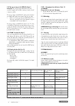
12.3 Changing oil (Fig. 4, 5, 15)
Change engine oil after 50 hours of operating time.
The engine oil change should be carried out while the engine
is at operating temperature.
1. Place the power generator/inverter on a level, even sur-
face.
2. Remove the ignition key (B) from the ignition lock (14).
3. Remove the cover (4) as described in 9.3 (Fig. 4).
4. Provide a suitable collection container (not included in the
scope of delivery).
5. Remove the oil drain plug (31) and remove the oil dipstick
(19).
6. Remove the oil drain screw (30) with a 10 mm open-end-
ed spanner (not included in the scope of delivery) to allow
the oil to drain off.
7. Screw the oil drain screw (30) back in.
8. Fill up with new engine oil (approx. 600 ml).
9. Screw the oil dipstick (19) in again.
10. Attach the oil drain plug (31) again.
11. Put the cover (4) on and fix in place by retightening the
two screws.
12. Dispose of the used oil properly.
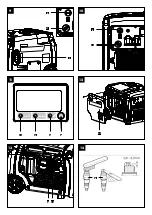
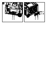
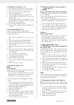
12.4 Air filter (33) (Fig. 12, 16)
NOTE!
Risk of damage!
Operating the engine without an air filter (33) or with a dam-
aged air filter can cause engine damage.
- Never run the engine without the air filter (33) or with a
damaged air filter. This would allow dirt into the engine,
which would result in severe damage to the engine.
Clean the air filter (33) every 50 operating hours, replace if
necessary.
1. Remove the engine cover (27) by loosening the three
screws with the Phillips screwdriver (F) provided (Fig. 12).
2. Remove each of the two wing nuts (32a) and two washers
(32b) on the air filter cover (32) (Fig. 16).
3. Remove the air filter cover (32).
4. Remove the air filter (33).
5. Do not use harsh cleaners or petrol to clean the air filter (33).
6. Clean the air filter (33) by knocking it on a flat surface.
If heavily soiled, wash with soapy water, then rinse with
clean water and allow to air dry.
7. The re-assembly takes place in reverse order.
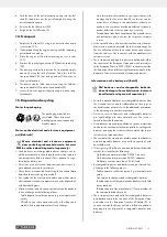
12.5 Charge the battery (17) with a car battery
charger (Fig. 1, 3
)
m
DANGER!
Danger due to charging the battery incorrectly!
If the charging voltage is too high, there is a risk of the bat-
tery (17) exploding.
Always remove the ignition key (B) from the ignition (14)
when working on the battery (17).
- The charging current of the battery charger must not exceed
5 A and the charging voltage must not exceed 14.4 V.
1. Remove the battery (17) as described in Section 13.2.
2. Connect the battery (17) to a suitable car battery charger.
Then connect the red cable to the positive pole (+) and the
black cable to the negative pole (-) of the charging unit.
3. Charge the battery (17) for at least 5 hours.
Attention!
Danger of short circuit!
- To avoid a short circuit, always disconnect the negative ca-
ble (-) from the battery (E) first and reconnect it last.
- When connecting/disconnecting the battery connection ca-
ble (17a), make sure that the poles (+/-) do not touch each
other and/or the frame.
12.6 Spark plug (28) (Fig. 12 - 14)
m
ATTENTION: Only replace the spark plug when
the engine is cold!
Check the spark plug (28) for contamination for the first time
after 20 operating hours and clean it with a copper wire brush
if necessary. Then service the spark plug (28) every 50 oper-
ating hours.
1. Remove the engine cover (27) by loosening the three
screws with the Phillips screwdriver (F) provided (Fig. 12).
2. Pull off the spark plug connector (29) with a twisting motion.
3. Remove the spark plug (28) with the enclosed spark plug
wrench (D).
4. Remove any dirt from the base of the spark plug (28).
5. Visually inspect the spark plug (28). Remove any deposits
present using a wire brush.
6. Check the spark plug gap. Set the electrode gap to 0.6 to
0.7 mm with a feeler gauge.
7. The re-assembly takes place in reverse order.
NOTE
A loose spark plug (28) can overheat and cause damage to
the engine. Tightening the spark plug (28) too much can dam-
age the thread in the cylinder head.
12.7 Cleaning the fuel filter insert (20) (Fig. 6)
Note:
The fuel filter insert (20) is a filter cup which is located
directly under the fuel filler cap (2) and filters all the fuel filled
in.
1. Unscrew the fuel filler cap (2). The fuel filler cap (2) is
connected to an anti-loss device in the fuel tank (21) and
thus cannot fall off.
2. Remove the fuel filter insert (20). Clean it in a non-flam-
mable solvent or a solvent with a high flash point.
3. Reinsert the fuel filter insert (20).
4. Retighten the fuel filler cap (2).
Summary of Contents for PISE 3400 A1
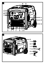
Page 3: ...1 4 3 1 2 5 7 8 9 10 11 13 14 15 16 12 6 2 A B C D E F G...
Page 4: ...5 19 4 B 4 4 B 7 11 B 6 21 2 20 22 8 11 B 3 B 17b 17a 17 10 17c 18...
Page 5: ...9 3 11 B 10 11 B 13 28 29 12 27 Low Oil Overload Disp 11 23 24 25 26 14 28...
Page 6: ...16 33 32 15 30 31 32b 32a...
Page 117: ...111 18 18 18 18 18 18 18 18 18 18 18 18 18 18 18 18 18 18 18 18 18 18 18...
Page 119: ......

