I E
G B
N I
1 3
Fill water into the water tank
.
the drain opening of the water
tank (13).
2. Fill water into the water tank (13)
up to the water level mark
.
Operation
Caution! Risk of injury!
- Always disconnect the plug from
the mains socket before working.
- Use only grinding discs and acces-
sories recommended by the manu-
.
tools and other accessories may
cause risk of injury.
- Only use grinding tools which
bear information about the manu-
facturer, type of binding, dimen-
sion and permitted number of
revolutions.
- Only use grinding discs where
the printed rotational speed is at
least as high as what has been
the device.
- Do not use broken, cracked or oth-
erwise damaged grinding discs.
- Never operate the device without
the visual protection disc.
- Always inspect the grinding disc
before starting the device:
Check the distance between
the spark protection holder and
grinding disc as well as work-
piece support and grinding disc
(distance maximum 2 mm).
-
placed once the spark protection
holder and workpiece support
on the grinding disc do not have
distance of max. 2 mm.
- Switch on the equipment only
when it is safely installed on the
work surface.
Keep your hands away from
the grinding disc when the
device is in operation. Injury
hazard!
Despite the spark protection, you
should always wear protective
glasses when working in order to
avoid eye injuries.
Switching on and off
Ensure that the mains voltage
rating plate.
Connect the equipment to the mains.
.
I
(
8) and the device starts up.
.
0
(
8) and the device switches off.
After switching on the device, wait until the
device has reached its max. speed. Only
then must you start with the grinding.
The disc will continue to
run after the equipment is
switched off. There is a risk
of injury.
Test run:
Before starting work and after each
change of grinding disc, carry out a test
run of at least 60 seconds with no load.
Switch off the equipment immediately if the
disc runs lumpy, substantial vibrations oc-
cur, or abnormal noises are generated.
Summary of Contents for PNTS 250 B1
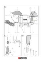
Page 3: ...max 2 mm 1 4 5 4 7 8 9 11 10 12 6 3 2 13 7 6 6 5 14 15 16 17 21 20 18 19 ...
Page 4: ...22 5 23 24 24 4 23 22 5 25 11 13 9 10 13 ...
Page 37: ...37 ...
Page 38: ...38 ...
Page 40: ...40 ...
Page 42: ...13 13a 13a 13c 13d 13b 22 1 26 28 29 27 28 22 1 ...
Page 43: ......


