background image

10

GB

IE

NI

in the attachment tool must fit 

the mounting diameter of the 

flange. 

Attachment tools which cannot 

be precisely attached to the electric tool 

turn unevenly, vibrate very strongly and 

can ultimately lead to a loss of control.

•  Never use damaged attachment 

tools. Check attachment tools 

such as grinding discs for chip-

ping or cracks, grinding plates 

for cracks, wear or strong abra-

sion and wire brushes for loose 

or broken wires before using 

them. If the electric tool or the 

attachment tool falls off, check 

whether it is damaged or, use 

an undamaged attachment tool. 

If you have checked the attach-

ment tool and attached it, keep 

yourself and any nearby persons 

beyond the level of the rotating 

attachment tool and allow the de-

vice to run for 1 min. at the high-

est rotational speed. 

Damaged tools 

usually break during this test period.

•  Wear personal safety equip

-

ment. Depending on the appli-

cation, use full face shields, eye 

protection or safety goggles. In 

so far as it is appropriate, wear 

dust masks, ear protection, 

gloves or special aprons which 

keep small grinding and materi-

al particles away from you. 

Eyes 

should be protected from the foreign 

matter which can be caused to fly du

-

ring the various applications. Dust or 

breathing masks should filter the dust 

that is created during operation. If you 

are exposed to loud noise for a long 

time, you may suffer hearing loss.

•  Ensure that other people are at 

a safe distance to your working 

area. Anyone who enters the 

working area should wear per-

sonal protective equipment. 

Bro-

ken bits from the piece being worked or 

broken attachment tools can fly away 

and cause injuries even beyond the di-

rect working area.

•  Hold the electric tool only by the 

insulated gripping surfaces when 

performing work in which the 

cutting tool may come into contact 

with hidden wiring or its own 

cord. 

Contact with a live wire can also 

cause a charge in metal parts of the 

device and result in an electric shock.

•  Keep the cord away from the ro-

tating attachment tool. 

If you lose 

control of the device, the power cord 

can become separated or caught and 

your hand or arm may be pulled into 

the rotating attachment tool.

•  Never put the electric tool down 

before the attachment tool has 

come to a full stop. 

The rotating at-

tachment tool can come into contact with 

the surface upon which it is set, whereby 

you could lose control of the electric tool.

•  Never allow the electric tool to 

run while you are carrying it. 

Your clothing may accidentally come 

into contact with the rotating attachment 

tool and get caught and the attachment 

tool could drill into your body.

•  Clean the ventilation slots of 

your electric tool routinely. 

The 

motor air pulls dust into the housing 

and, should too much metallic dust coll-

ect, could cause electrical hazards.

•  Never use the electric tool near 

flammable material. 

Sparks could 

ignite this material.

•  Do not use attachment tools 

which require liquid coolant. 

Using water or another liquid coolant 

could lead to electrical shock.

Summary of Contents for PWS 125 C3

Page 1: ...ANGLE GRINDER PWS 125 C3 WINKELSCHLEIFER Originalbetriebsanleitung ANGLE GRINDER Translation of the original instructions IAN 275389...

Page 2: ...ebsanleitung Seite Before reading unfold the page containing the illustrations and familiarise yourself with all functions of the device Klappen Sie vor dem Lesen die Seite mit den Abbildungen aus und...

Page 3: ...1 2 3 4 8 9 7 5 6 11 12 13 14 19 18 17 22 21 20 15 16 25 24 23 10 3...

Page 4: ...Translation of the original EC declaration of conformity 49 Introduction Congratulations on the purchase of your new device With it you have chosen a high quality product During production this equip...

Page 5: ...Overview 1 Handgrip 2 Threads for handgrip 3 Speed regulator 4 Switch block 5 On off switch 6 Maintenance coverage 7 Screw 8 Threads for handgrip 9 Spindle stop button 10 Power plug 11 Cutting disc 1...

Page 6: ...dicated vibration emission value may also be used for an introductory assessment of the exposure Warning The vibration emission value whilst actually using the electrical tool may vary from the given...

Page 7: ...body contact with earthed or grounded surfaces such as pipes radiators ranges and ref rigerators There is an increased risk of electric shock if your body is earthed or grounded Do not expose power to...

Page 8: ...tarting Ensure the switch is in the off position before connecting to power source and or battery pack picking up or carrying the tool Carrying power tools with your finger on the switch or energising...

Page 9: ...This will ensure that the safety of the power tool is maintained Safety instructions for all applications Common safety instructions for grinding sanding working with wire brushes polishing and cutti...

Page 10: ...at other people are at a safe distance to your working area Anyone who enters the working area should wear per sonal protective equipment Bro ken bits from the piece being worked or broken attachment...

Page 11: ...red due to functional reasons Therefore proceed cautiously and hold the workpiece firmly in order to avoid slipping which could cause your hands to come into contact with the grinding disc The workpie...

Page 12: ...ons b Never bring your hands near a rotating attachment tool The attachment tool can run over your hand in the kickback c Keep your body away from the area in which the electric tool would move during...

Page 13: ...r you interrupt your work switch the device off and hold it until the disc has come to a full stop Never try to pull the cutting disc out of the cut while it is still running because it can kick back...

Page 14: ...only moderate pressure on the work piece Move the device evenly back and forth A working angle of 30 to 40 achieves the best results for scrub grinding Cutting disc Never use a scrubbing wheel for cut...

Page 15: ...4 Set the desired disc onto the mounting flange 15 label on the disc should always face the device 5 Set the clamping nut 16 on the mounting spindel 17 again The flat side of the clamping nut must fac...

Page 16: ...ing flange and the grinding tools must be made of elastic materials e g rubber soft cardboard etc Always reassemble the device completely after replacing the grinding disc Switch the device off and re...

Page 17: ...cloth Servicing Replacing carbon brushes Switch off the appliance and dis connect the power supply Let the appliance cool down 1 Loosen the screw 7 of the maintenance cover 6 2 Remove the maintenance...

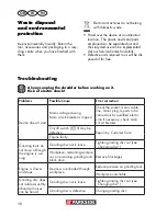
Page 18: ...ools block drive Remove blockages Engine is slower and stops Device is overloaded through workpiece Reduce pressure on grinding tool Workpiece unsuitable Grinding disc does not rotate smoothly abnorma...

Page 19: ...g speed n0 max 12200 min 1 Disc speed max 80 m s Outer diameter 125 mm Bore hole 22 23 mm Thickness cutting roughing discs max 6 mm Flap disc Item No 91103211 Idling speed n0 max 12200 min 1 Disc spee...

Page 20: ...antee you will receive either the repaired product or a new product No new guarantee pe riod begins on repair or replacement of the product Guarantee Period and Statutory Claims for Defects The guaran...

Page 21: ...ctions below Please have the receipt and item num ber IAN 275389 ready as proof of purchase for all enquiries Please find the item number on the rat ing plate Should functional errors or other de fect...

Page 22: ...or by bulky goods express or other special freight will not be accepted We will dispose of your defective devices free of charge when you send them to us Service Center GB Service Great Britain Tel 08...

Page 23: ...nleitung Herzlichen Gl ckwunsch zum Kauf Ihres neuen Ger tes Sie haben sich damit f r ein hochwertiges Ger t entschieden Dieses Ger t wurde w hrend der Produkti on auf Qualit t gepr ft und einer Endko...

Page 24: ...ifer ist zum Trennen Schruppen oder B rsten von Metall ge eignet F r die einzelne Anwendung sind jeweils spezielle Scheiben vorgesehen Beachten Sie die Angaben der Scheiben hersteller Die Funktion der...

Page 25: ...g gestellt werden k nnen daher nicht geltend gemacht werden Der angegebene Schwingungsemissions wert ist nach einem genormten Pr fver fahren gemessen worden und kann zum Vergleich eines Elektrowerkzeu...

Page 26: ...d auf akkubetriebene Elektrowerk zeuge ohne Netzkabel Arbeitsplatzsicherheit Halten Sie Ihren Arbeitsbereich sauber und gut beleuchtet Unord nung oder unbeleuchtete Arbeitsberei che k nnen zu Unf llen...

Page 27: ...ckdose zu ziehen Halten Sie das Kabel fern von Hitze l scharfen Kanten oder sich bewegenden Ger tetei len Besch digte oder verwickelte Kabel erh hen das Risiko eines elektrischen Schlages Wenn Sie mit...

Page 28: ...se angeschlossen sind und richtig verwendet wer den Verwendung einer Staubabsaugung kann Gef hrdungen durch Staub verrin gern Verwendung und Behandlung des Elektrowerkzeuges berlasten Sie das Ger t ni...

Page 29: ...r und oder schweren Verletzungen kommen Verwenden Sie kein Zubeh r das vom Hersteller nicht speziell f r dieses Elektrowerkzeug vor gesehen und empfohlen wurde Nur weil Sie das Zubeh r an Ihrem Elektr...

Page 30: ...en wegfliegen und Verletzungen auch au erhalb des direkten Arbeitsbereichs verursachen Halten Sie das Elektrowerkzeug nur an den isolierten Grifffl chen wenn Sie Arbeiten ausf h ren bei denen das Eins...

Page 31: ...n oder entflammbare Substanzen entz nden Tragen Sie beim Schleifen B rsten und Trennen stets eine Schutzbrille Sicher heitshandschuhe einen Atemschutz und einen Geh rschutz Halten Sie nie die Finger z...

Page 32: ...e Schleifscheibe im Werkst ck hakt oder blockiert kann sich die Kante der Schleif scheibe die in das Werkst ck eintaucht verfangen und dadurch die Schleifscheibe ausbrechen oder einen R ckschlag verur...

Page 33: ...ner zeigt Die Schutzhaube hilft die Bedienperson vor Bruchst cken zuf l ligem Kontakt mit dem Schleifk rper sowie Funken die Kleidung entz nden k nnten zu sch tzen d Schleifk rper d rfen nur f r die e...

Page 34: ...ibe zu ver mindern Gro e Werkst cke k nnen sich unter ihrem eigenen Gewicht durchbiegen Das Werkst ck muss auf beiden Seiten der Scheibe abgest tzt werden und zwar sowohl in der N he der Trennscheibe...

Page 35: ...ruck auf das Werkst ck aus Bewegen Sie das Ger t gleichm ig hin und her Bei einem Arbeitswinkel von 30 bis 40 erzielen Sie beim Schruppschleifen das beste Ergebnis Trennschleifen Verwenden Sie niemals...

Page 36: ...Sie die Spindel Arretier taste 9 2 Drehen Sie die Aufnahmespin del 17 bis die Spindel Arretierung die Aufnahmespindel fixiert Halten Sie die Spindel Arretiertaste 9 weiter ge dr ckt 3 L sen Sie die Sp...

Page 37: ...er als die Bemessungs Leerlaufdrehzahl des Ger tes ist Vergewissern Sie sich dass die Ma e der Schleifscheibe zum Ger t passen Benutzen Sie nur einwandfreie Schleifscheiben Klangprobe sie haben beim...

Page 38: ...Originalteile Lassen Sie das Ger t vor allen Wartungs und Reinigungsar beiten abk hlen Es besteht Verbrennungsgefahr Kontrollieren Sie das Ger t vor jedem Gebrauch auf offensichtliche M ngel wie lose...

Page 39: ...er tes Die Kohleb rsten sind grunds tzlich paarweise auszu tauschen Lagerung Bewahren Sie das Ger t an einem trockenen und staubgesch tzten Ort auf und au erhalb der Reichweite von Kindern Schleifsche...

Page 40: ...Motor defekt Schleifwerkzeug bewegen sich nicht obwohl Mo tor l uft Schleifscheiben Mutter locker Schleifscheiben Mutter anziehen siehe Scheibe wechseln Werkst ck Werkst ckreste oder Reste der Schlei...

Page 41: ...digkeit max 80 m s Au endurchmesser 125 mm Bohrung 22 23 mm St rke Trenn Schruppscheiben max 6 mm F cherschleifscheibe Art Nr 91103211 Leerlaufgeschwindigkeit n0 max 12200 min 1 Scheibengeschwindigkei...

Page 42: ...ariert oder ersetzt Diese Garantieleis tung setzt voraus dass innerhalb der Drei Jahres Frist das defekte Ger t und der Kauf beleg Kassenbon vorgelegt und schriftlich kurz beschrieben wird worin der M...

Page 43: ...hild Sollten Funktionsfehler oder sonstige M ngel auftreten kontaktieren Sie zun chst die nachfolgend benannte Serviceabteilung telefonisch oder per E Mail Sie erhalten dann weitere In formationen ber...

Page 44: ...dl at IAN 275389 CH Service Schweiz Tel 0842 665566 0 08 CHF Min Mobilfunk max 0 40 CHF Min E Mail grizzly lidl ch IAN 275389 Importeur Bitte beachten Sie dass die folgende Anschrift keine Serviceansc...

Page 45: ...45...

Page 46: ...46...

Page 47: ...1 2009 A11 2010 EN 60745 2 3 2011 A12 2014 EN 55014 1 2006 A2 2011 EN 55014 2 1997 A2 2008 EN 61000 3 2 2014 EN 61000 3 3 2013 Die alleinige Verantwortung f r die Ausstellung dieser Konformit tserkl r...

Page 48: ...48 2016 07 20 rev02 TR...

Page 49: ...standards and stipulations have been applied EN 60745 1 2009 A11 2010 EN 60745 2 3 2011 A12 2014 EN 55014 1 2006 A2 2011 EN 55014 2 1997 A2 2008 EN 61000 3 2 2014 EN 61000 3 3 2013 This declaration of...

Page 50: ...GRIZZLY TOOLS GMBH CO KG Stockst dter Stra e 20 D 63762 Gro ostheim Last Information Update Stand der Informationen 07 2016 Ident No 72037129072016 GB IE NI IAN 275389...

Reviews: